This is a cautionary tale about the risks in getting the local guys or your friend with a welder to work on your E-Type…
An E-Type is assembled with 95% resistance spot-welding, and about 5% gas-welding on the seams and corners, with a little braze thrown in here and there on the corners as well. The order that the shells were originally assembled in is a logical one based on the structure of the shell, but also the requirements of being able to access the seams. As you assemble one with the spot-welder, you are constantly thinking, “OK, I have to do this, THEN this, THEN that…” – otherwise, you essentially build yourself out of the ability to reach a given seam with the spot-welder tongs.
For that reason, when we restore E-Type shells, we are often faced with having to weld a seam that is now in a area we cannot reach with the tongs. And many people don’t realize that you can’t just “get longer or bigger tongs” – once you go past about 18″, you lose so much amperage AND clamping pressure, that you can’t get a good weld.
SO – we find ourselves doing ALOT of “plug-welding” in areas that are now too far into the shell. This method consists of drilling a series of holes in one panel, and then fitting it against the other, then coming in with a MIG or TIG welder and filling in the hole, picking up both panels in the process – and that last part is the real trick – ESPECIALLY for amateur welders using a MIG…
Many do-it-yourselfers at home or local shops will use plug-welding exclusively, simply because they don’t have a spot-welder. And what happens to these guys is that the wire is coming out too fast, and with their limited experience they start to panic and fill the hole without ever really grabbing the lower panel – we see this ALL THE TIME on previously restored E-Types! OR – they weld very “timidly” – doing fast little hits on the trigger and filling in the hole with a little series of tacks – that doesn’t work either. In that sense, they are doing what all of my friends would do when I taught them to weld. I would constantly be telling them, “Look, it’s not a hot glue gun… Your job is to take these two pieces of metal and fuse them into one using electricity – it’s NOT to “glue” them together with little globs of molten steel.” – but sadly, that’s EXACTLY what we see on alot of E-Type shells that come in here – even from other shops…
This blog shows what happens when plug-welding is poorly executed. Whether you bring your shell here, somewhere else, or do the work yourself, make sure the person doing the welding knows what they are doing – and that usually means about 20 years of experience – minimum. Otherwise, you are LITERALLY risking your life with poor welding – take a look at the welds on these floors:
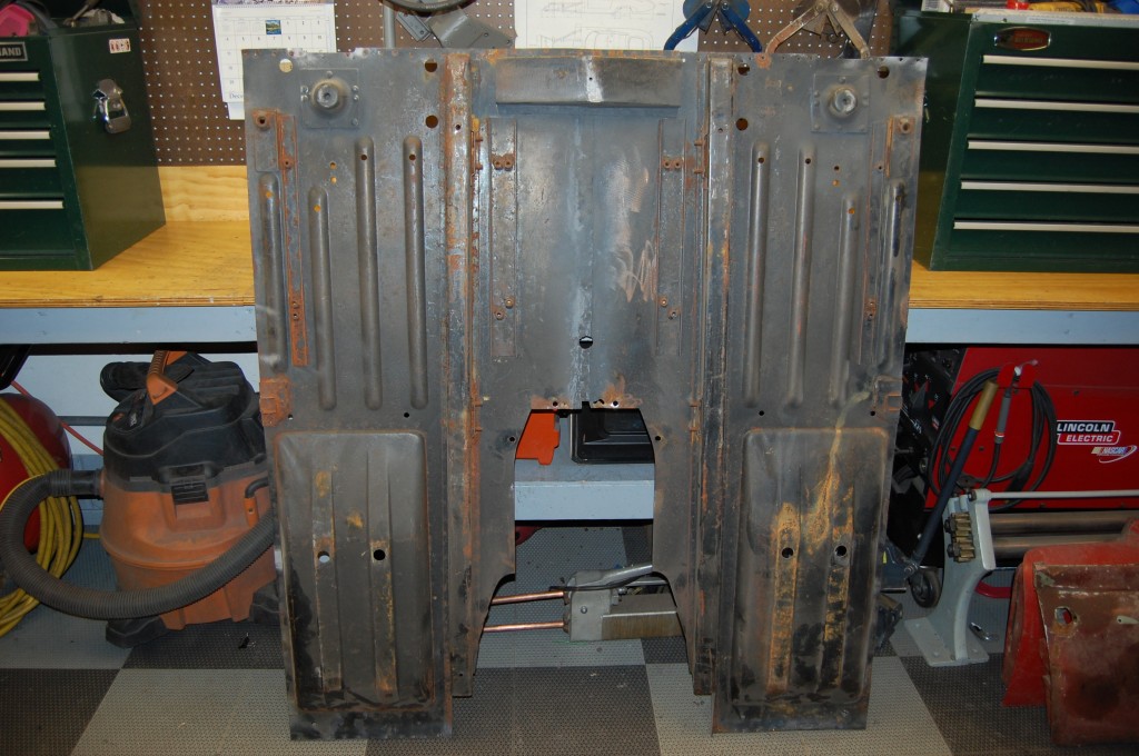
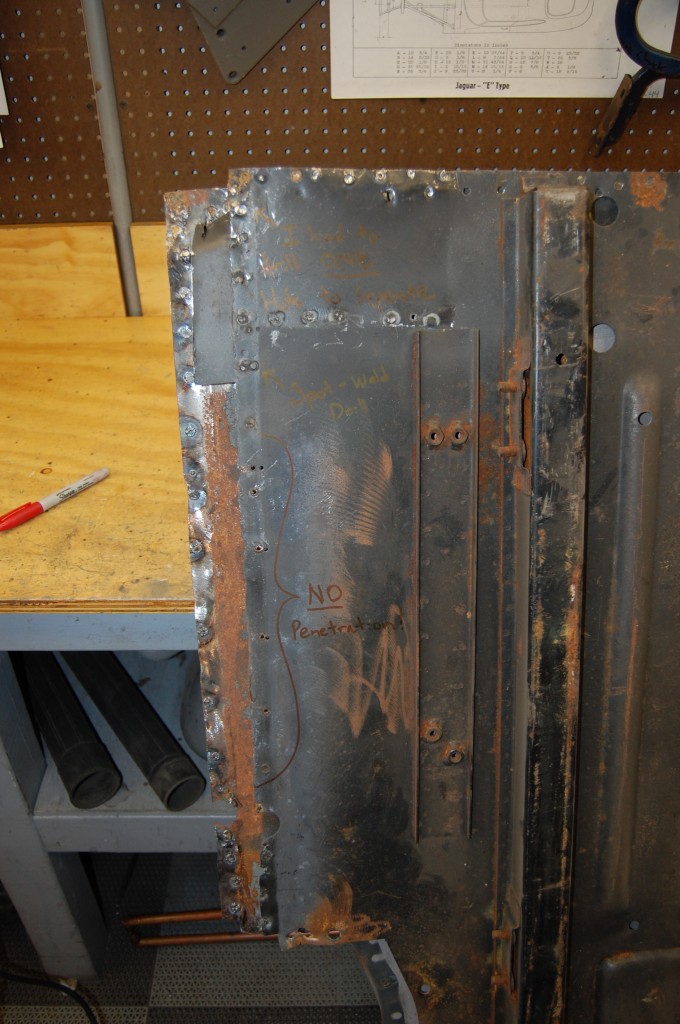
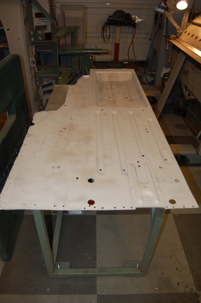
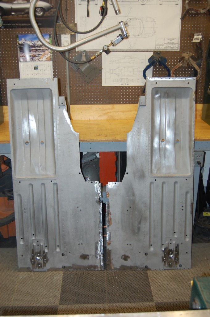
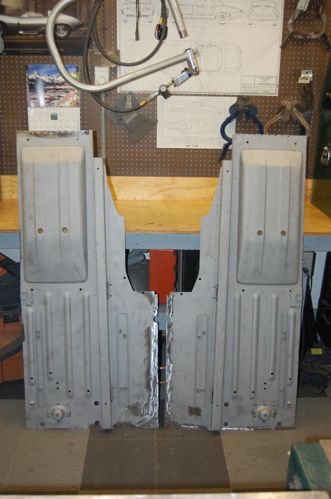
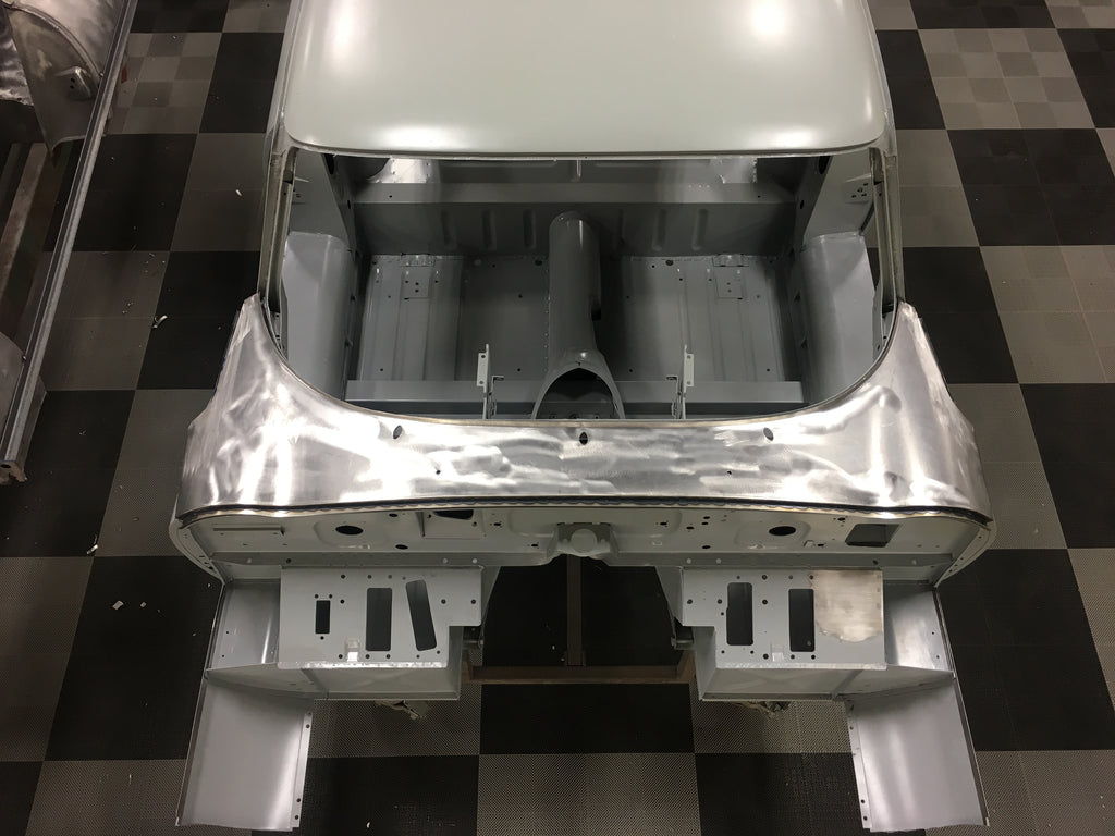
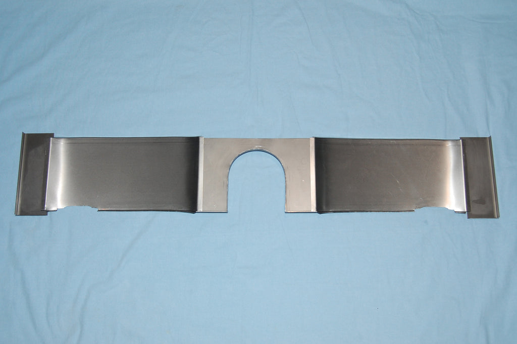
- This is a pair of new MR floors that were partially installed in a ’69 OTS shell that we purchased as an abandoned project. That shell is destined for some custom drive-train and floor work, so we have removed these floors and will clean them up for use in another shell. Other than a few tacks and spots here and there, they are new.
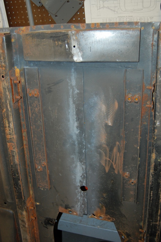
- Our first order of business in “restoring” the new floors is to remove the tie plate, and seperate the floors. We can see that they have been welded together with a combination of spot-welds on the edge (probably the only place where their cheapo spot-welder with stubby little tongs could reach), and plug-welds deeper into the panel – and the plug welds look messy, so it might be REAL TOUGH to get these floors apart with screwing them up…
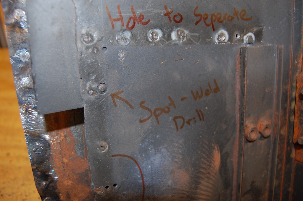
- …or maybe not! After drilling out the spot-welds on the edge, I could see light coming through the lower seam, and as I pulled a little harder with my hand, BANG! – the whole thing popped right off!
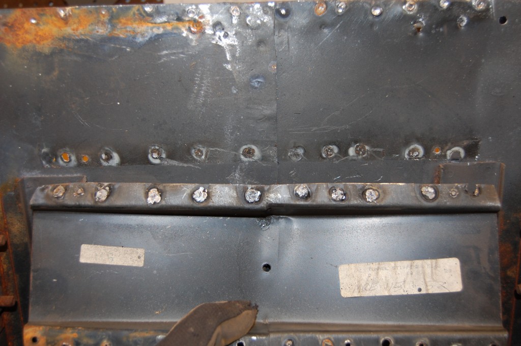
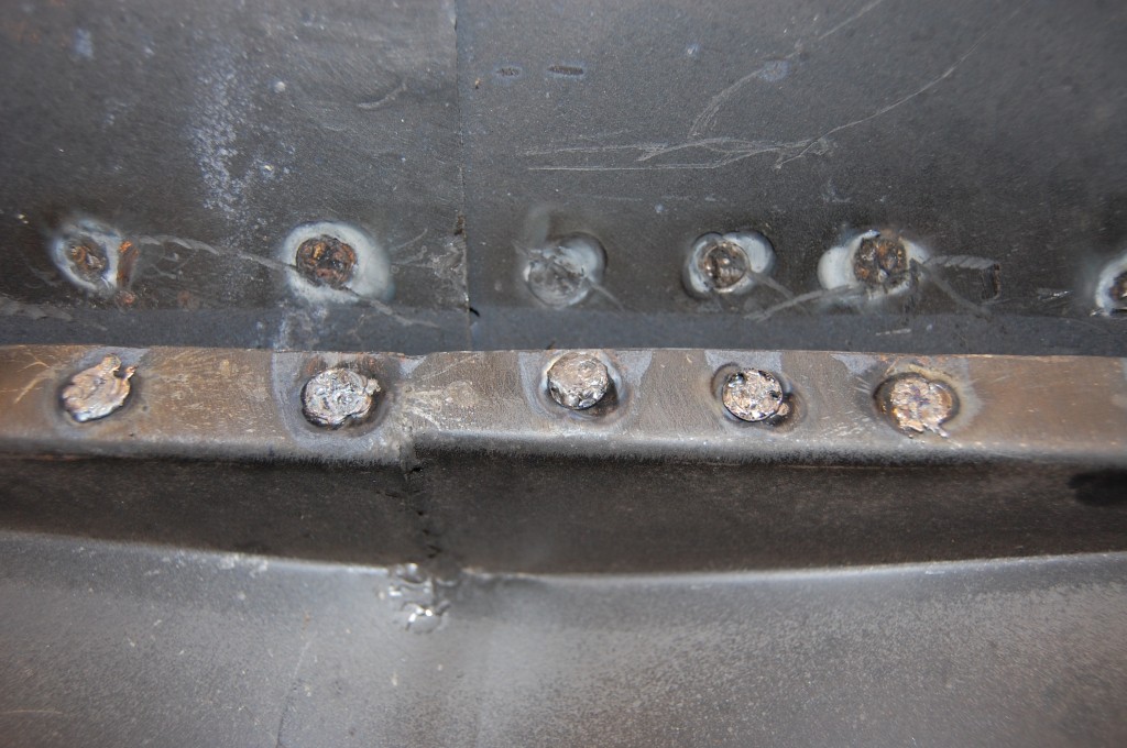
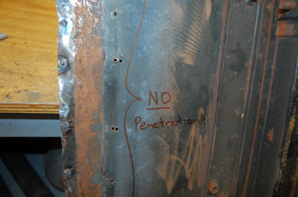
- Here’s the reason – ZERO penetration on these plug welds! What happened here was that the plug-weld was executed in a series of small blips from a MIG welder, with the lower panel in primer. That primer shielded the lower panel from the current, and the operator ended up filling the hole in the upper panel only! These welds look EXACTLY like someone trying to fill a hole in a single panel using a copper backing plate – in this case, their lower primed panel acted as that backing plate!
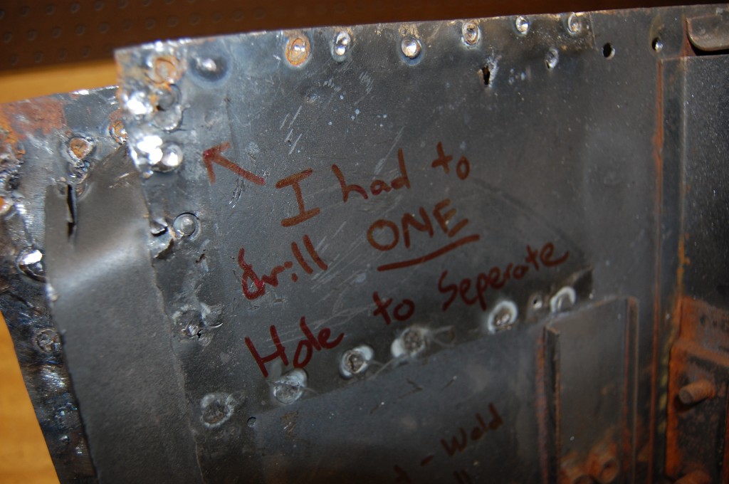
- And so the next thing you know, we drilled out one spot-weld in the end, and then I swear, pulled these two floors apart with our hands! The other side is behind this one, showing the two mated surfaces alongside each other.
- ONE spot weld was holding these floors together!
- And by the looks of it, they welded these floors together once already, then drilled them apart and started over!
- ZERO penetration!
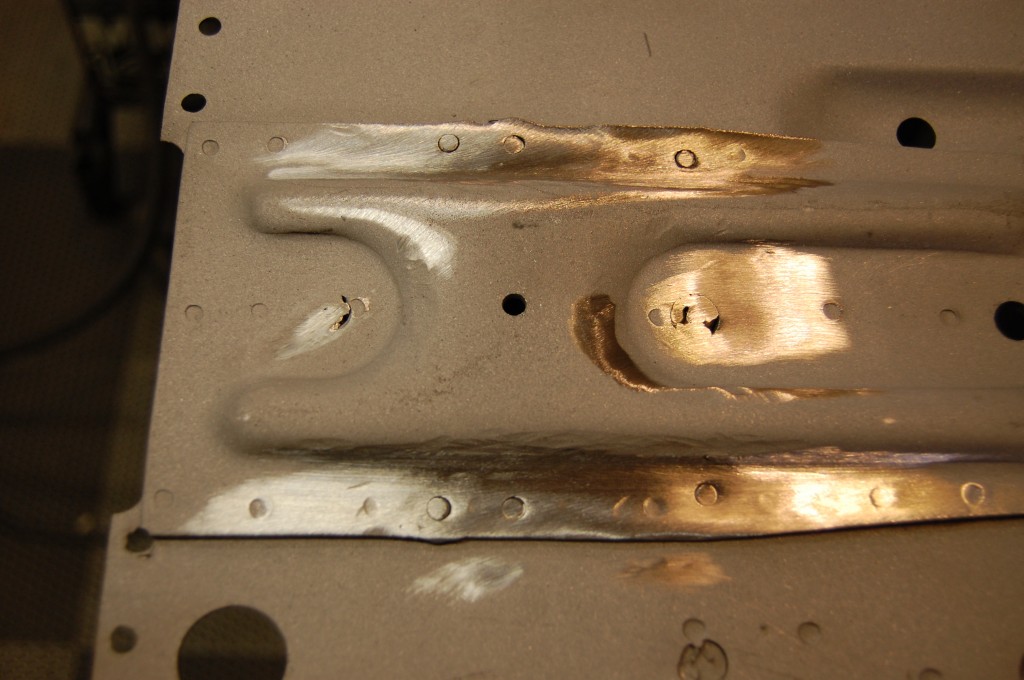
- After seperating, we blasted the floors bare. Next order of business is to properly weld the top sides of the radius cup rivets – they are also “glued”…
- We’ve ground down the radius cup rivets “welds”, and also welded up a few holes to make this panel new again.
- Look closely – after grinding down the lumpy welds, the rivets are not at all connected to the top plate.
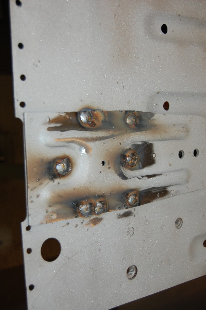
- We grabbed the MIG and cranked it up to weld these rivets to the top plate with some SERIOUS penetration. With air pockets, etc. in the old weld, we got some splatter.
- Finished! These floors are new – again – and ready for a new home in another E-Type!
- Note the blue rivets on the radius cups – the new welds have penetrated them fully, and you can see that they have turned blue from the heat. You can’t weld the radius cups to the floors – constant froce from the radius arms will cause stress cracks and they will eventually tear the whole upper plate out of the floor.

