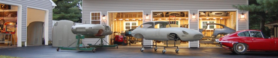
Well, there is a good reason I haven’t blogged much over the past year – I was busy running the business – and building this…
This blog will walk you through our new chassis table and E-Type alignment jigs. I had originally thought I might NEVER post photos of this – as alot of time and effort went into it and I didn’t want some other shop copying my designs. But now that it’s completed, I now know that only an insane person would build this thing in the first place!
Another reason it would be tough to copy are the dimensions… These don’t exist anywhere – and let me tell you right now – the crash sheets that are out there on E-Types have very little useful information, and what they do have is not correct anyway. In order to get the dimensions right, I learned that you need about a dozen E-Type body shells to measure and compare.
This was a true labor of love for me. I have been working on the design for this in my head almost since I started this business, and this was a chance to really use your head to design something with a real purpose behind it. As the years have gone by, I have become more and more particular and meticulous with the things that I build, but this took that to w WHOLE NEW LEVEL!
My goal was to have something that I could turn to that was simply “THE LAW” as far as any and all dimensions go. I have found over the years that you spend a ridiculous amount of time lining up panels and measuring and re-measuring as you go. And those measurements are EXTREMELY hard to make, as you are usually trying to measure between two points that have other things in the way…
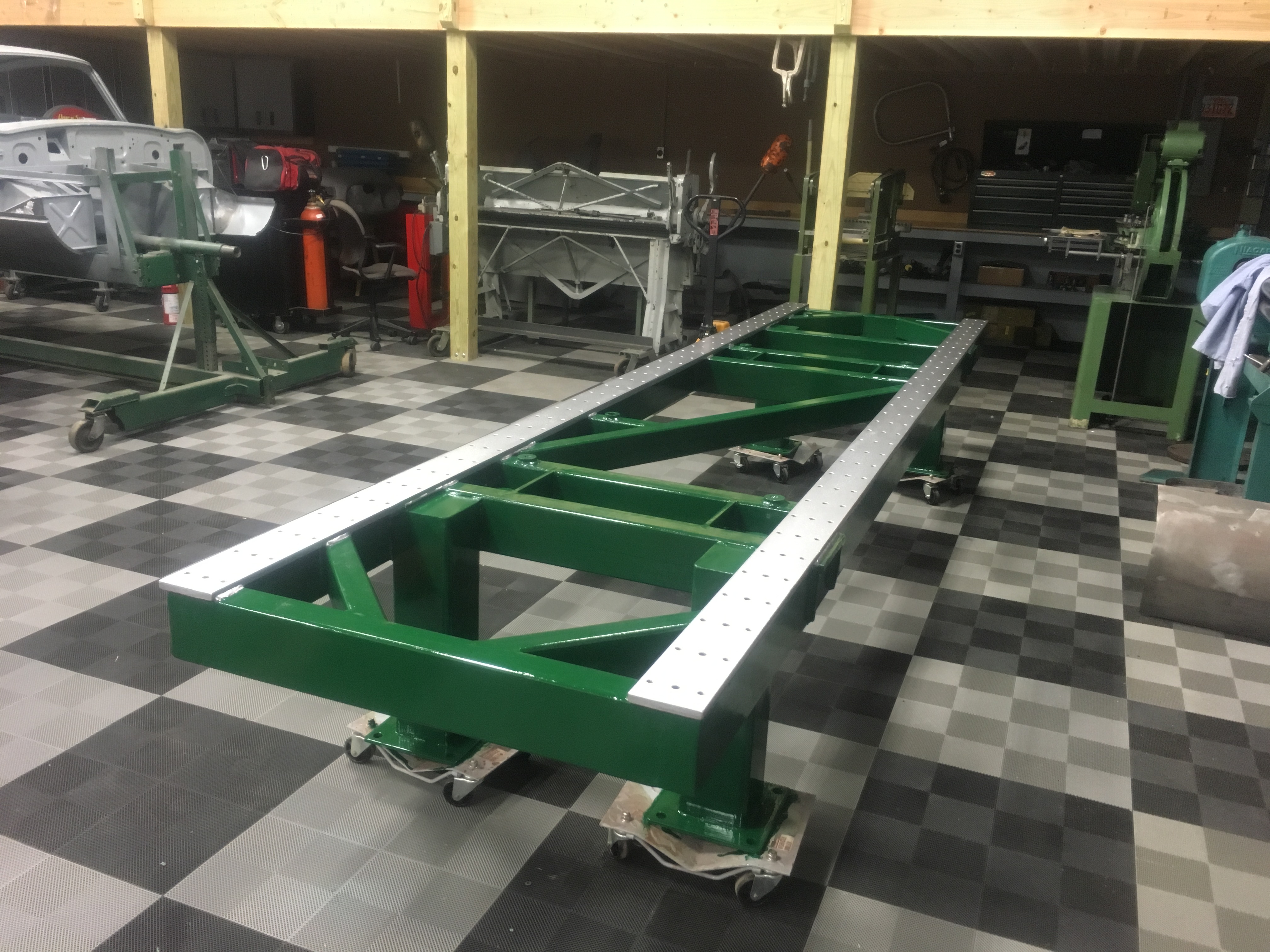
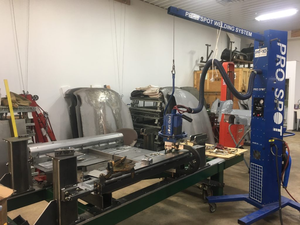
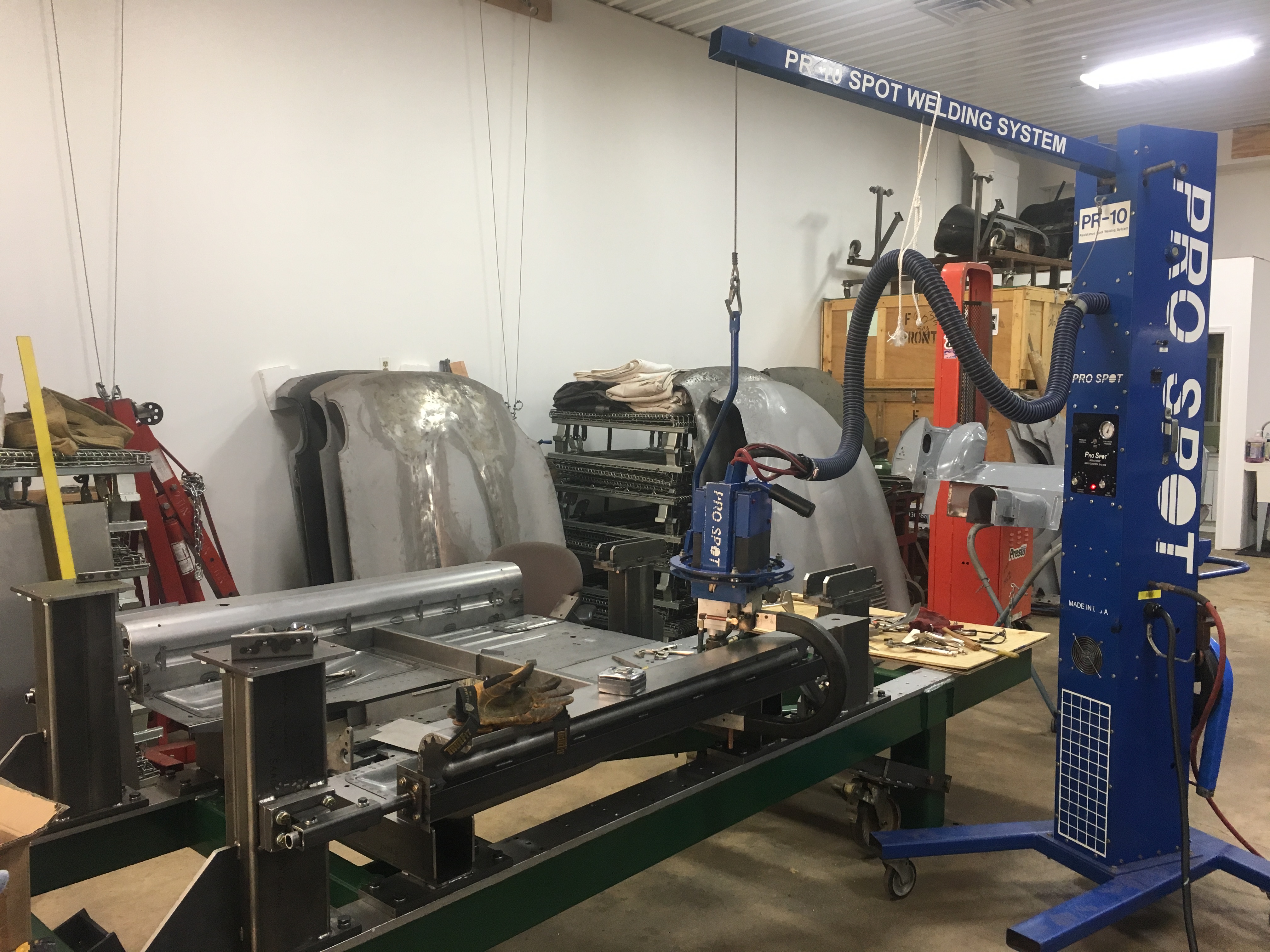
1 – So to begin with, you MUST have a known flat surface to work with. And I mean FLAT – not a poured concrete shop floor, or whatever else you can come up with – something real… We started with a surplus spot-welding trolley from the local GM plant. Now, THIS is flat! When you stick your eye on the edge of it and sight down the 140foot length, you have never seen anything so straight in your life! Lord only knows what it cost GM to have these built and then blanchard ground absolutely dead-on perfect…
2 – I wanted our jigs to be SOLID – absolutely 100% non-movable regardless of the force applied or the umber of years that we use them – so everything is ridiculously thick – and heavy!
3 – I wanted the jigs to be 100% un-movable in any direction when bolted down… That meant super thick base plates with mounting holes that were machined with ZERO clearance on the bolts, and the bolt pattern had to be absolutely perfect or they wouldn’t fit.
4 – I wanted not only the pickup points on the body shell to be in the absolutely perfect locations, but I also wanted every single portion of every jig – every base, every tower piece, every plate and every piece of tubing – to be absolutely perfectly aligned as well. This would allow me to reference perfectly straight surfaces all over the shell for future comparisons of surfaces of the shell while building. This meant that every joint and surface had to be not just cut, but machined to be on a perfect 90-degrees…
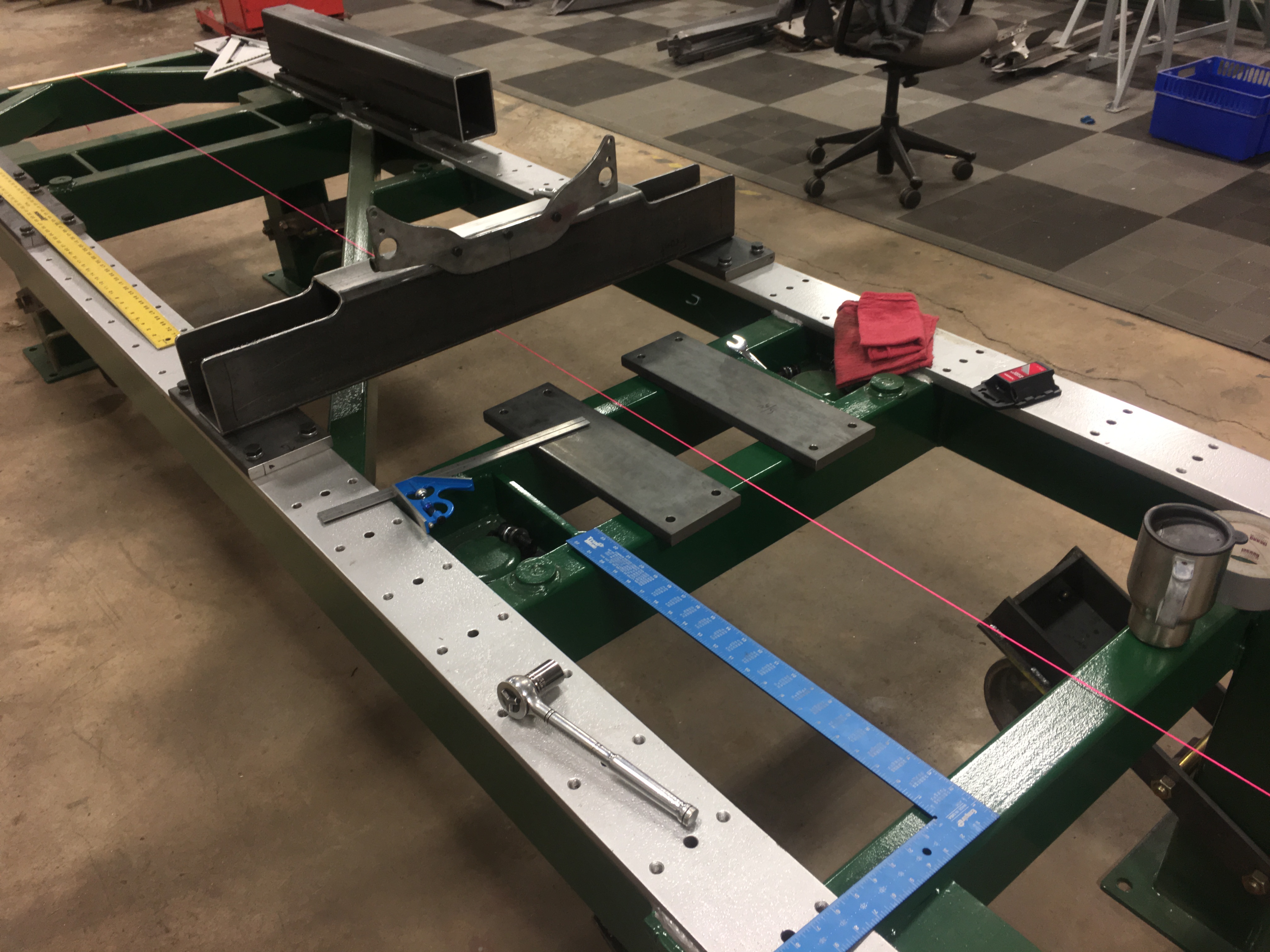
5 – In order to accomplish this precision, we had to TIG weld almost everything, AND have a way to be able to adjust out any alignment erros introduced in the welding. So we used a design for all jigs that included the use of shims at all attachment points and joints to allow for adjustment after the jigs were built. We were able to reference back to the table and change shims so that all measurements are 100% perfect.
6 – Adjustability – We built the jigs to be able to build E-Type body shells from scratch. That meat that we had to make things in sections that could be added as the shell was built up – AND had to have a design so that we could get the shell out once it was completed! But we also wanted to be able to mount any shell into it to align them properly during restoration. because we found that the factory had considerably more variation in some points than we desired, the shims will allow us to mount “imperfect” but original shells into the assembly.
7 – Tolerance – I am not a machinist, and so I don’t sweat a few thousandths of an inch here and there… But after this project, NOW, I am addicted to dimensions down to this degree of accuracy (that’s going to drive me crazy now for the rest of my life…) Ultimately, we built an E-Type jig that was more accurate than most of the measuring tools that I had at my disposal… By the end of the project, I was checking for a level of accuracy that was less than the thickness of the lines in the square I was using to check the dimensions!
My estimate is that it is true within 0.030″ (1/32″) across the entire 12 feet. After a year of exhaustively researching E-Type dimensions, I believe the cars were originally true within about 3/16″, or 0.188″. As you look through the photos below, notice that in almost every shot, there are multiple measuring devices laying around – the dedication to accuracy during the build was nothing short of fanatical.
I try to be modest about what we do here – let’s face it, no matter what you are doing, it seems that there is always someone out there doing it better… But I’m VERY proud of this creation – from the standpoint of precision, and insisting on “no compromises” in the construction – this is the greatest thing I have ever built.
And so, I believe that our new chassis table is now is the most precise E-Type body jig in existence. There are only a few others out there that are built similar to this – with this number of pickup points and of this strength – and I have seen photos of them and they just aren’t at this level of accuracy.
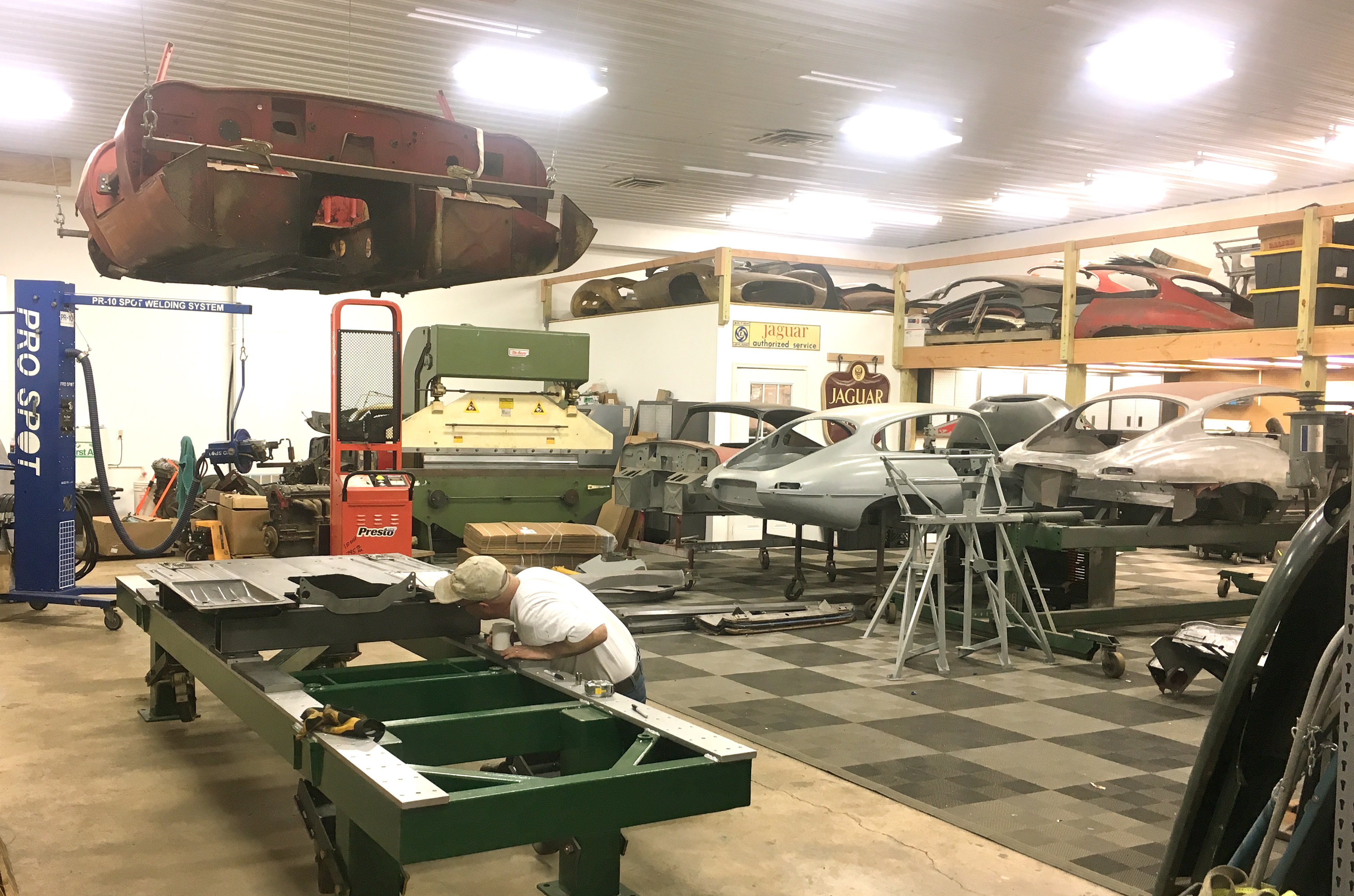
It took a full year to build all of the pieces, but throughout the year we had several different E-Type shells in and out of it. We also used it to build one partial shell that is being used for a lightweight low-drag replica, and also used it to straighten and rebuild a flat-floor OTS shell that was badly wrecked in the tail. It worked BEAUTIFULLY in all cases, and it is going to change the way that we restore shells, AND take the quality of our finished product to an even higher level!
Some shops have a rotisserie, some have a good flat frame table to work to – and that’s good! Some might even have a few basic E-Type jigs… None of them have this – it is 100% perfect Some parts of it might not seem very glamorous, and we haven’t painted the jigs yet (and maybe never will…), but if you’re a guy who spends his life on E-Type metalwork, trust me, this is a beautiful thing…
-

- Our starting point – the GM spot-welding trolley from the local plant. These were used to align the body panels of Chevrolet Berettas and Corsicas for robotic spot-welding. It is absolutely perfectly flat and straight.
-

- January 2017 – here I am just beginning to plan the design of the floor jigs.
-

- Another early shot that shows a great deal of alignment and measuring taking place.
-
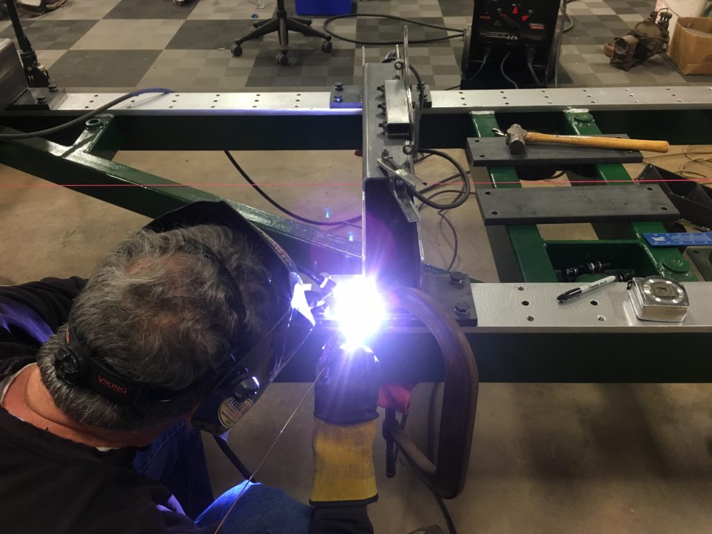
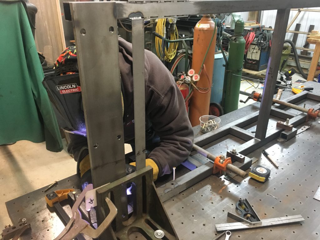
- This is Steve making the first of many TIG welds to ensure that any warpage during welding was avoided – or at least minimized. The thickness of all components also helped with that.

-
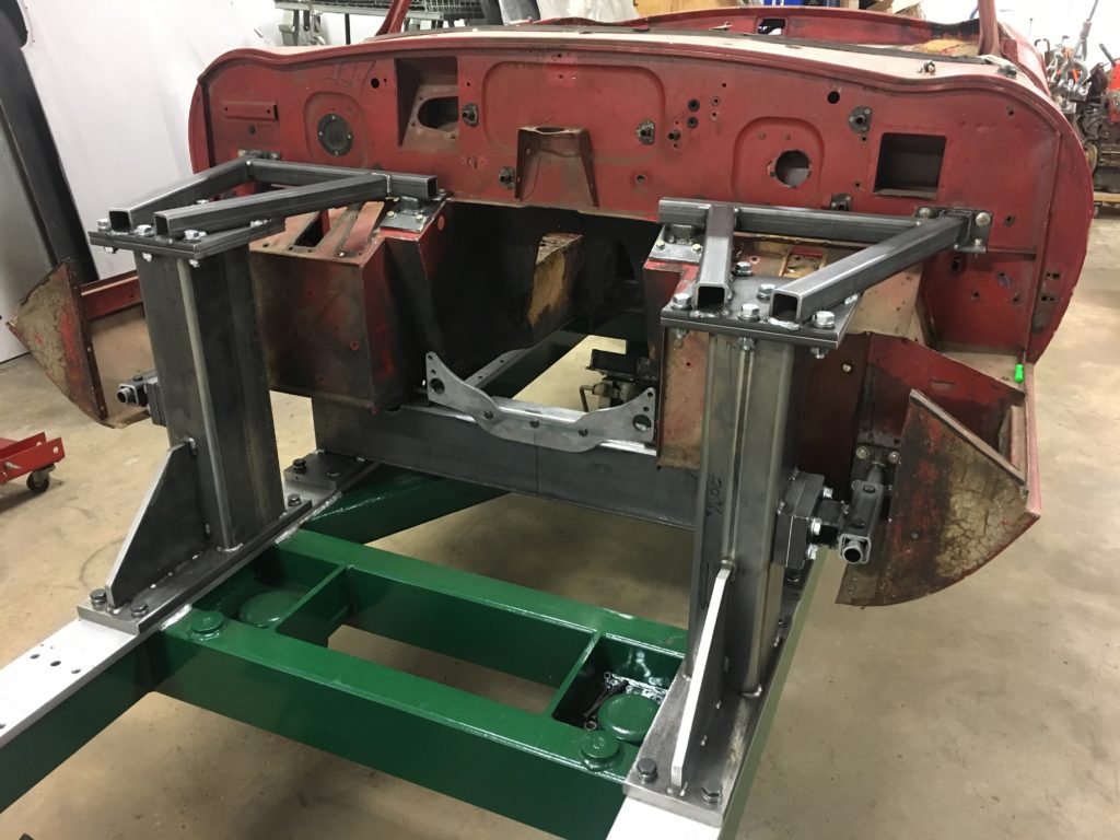
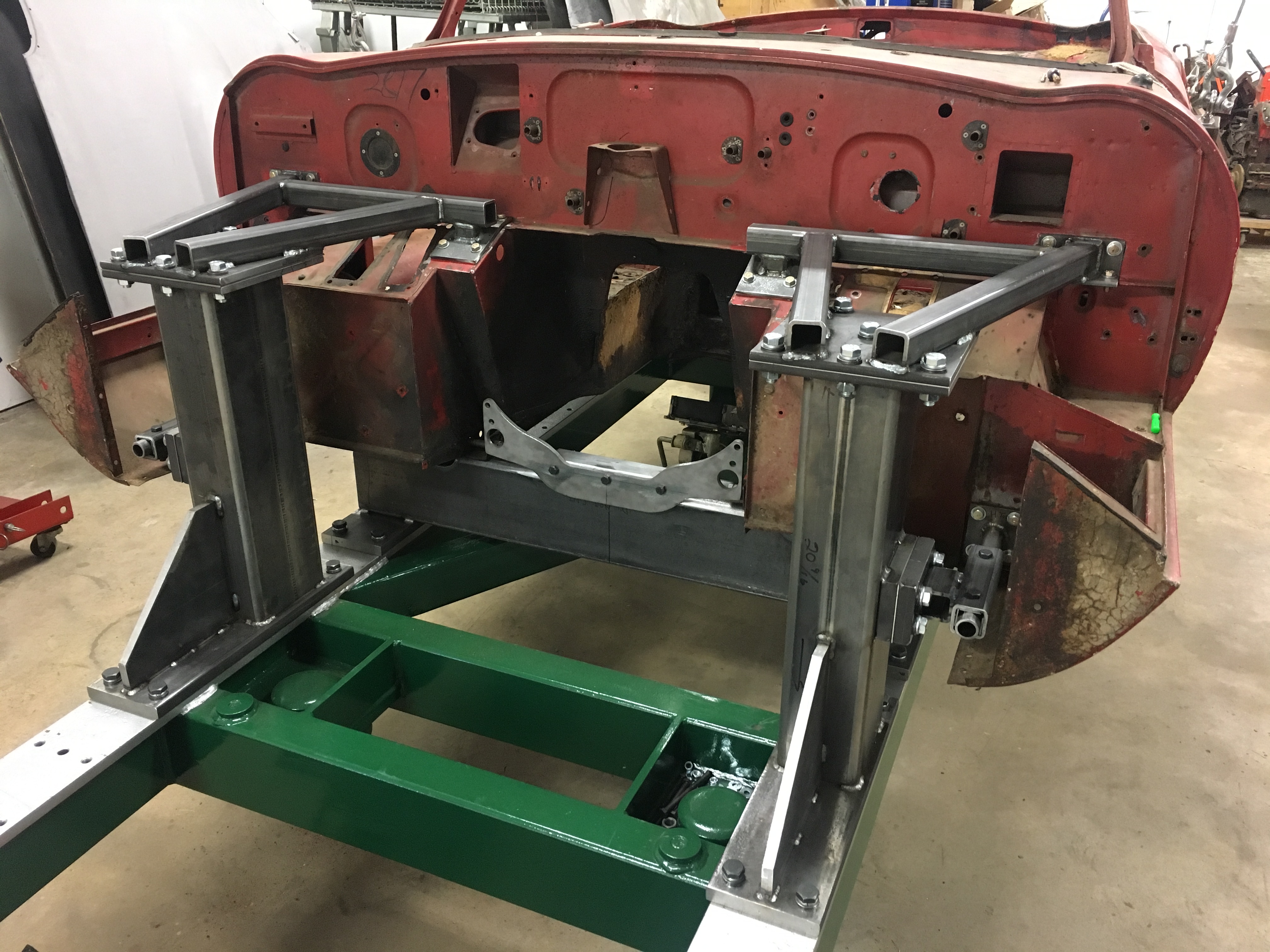
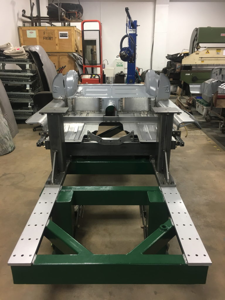
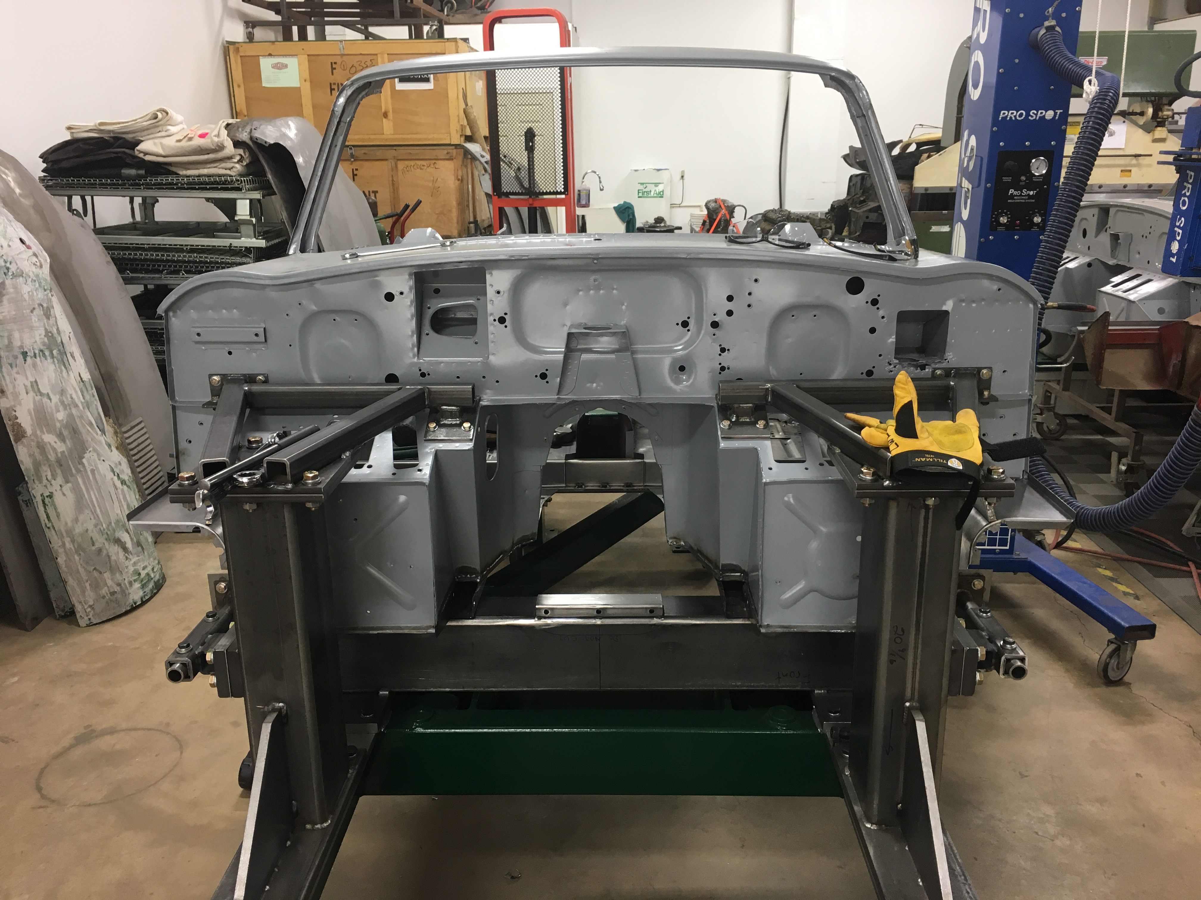
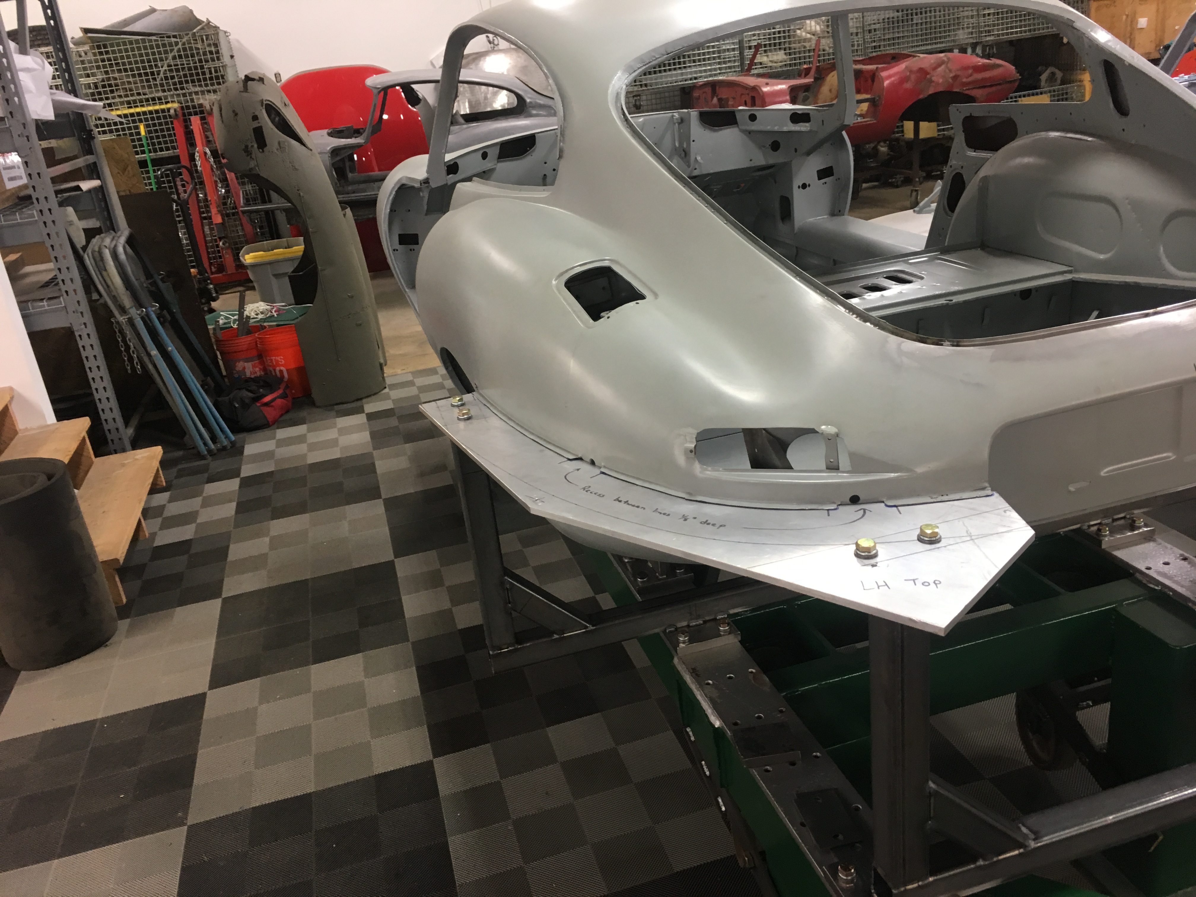
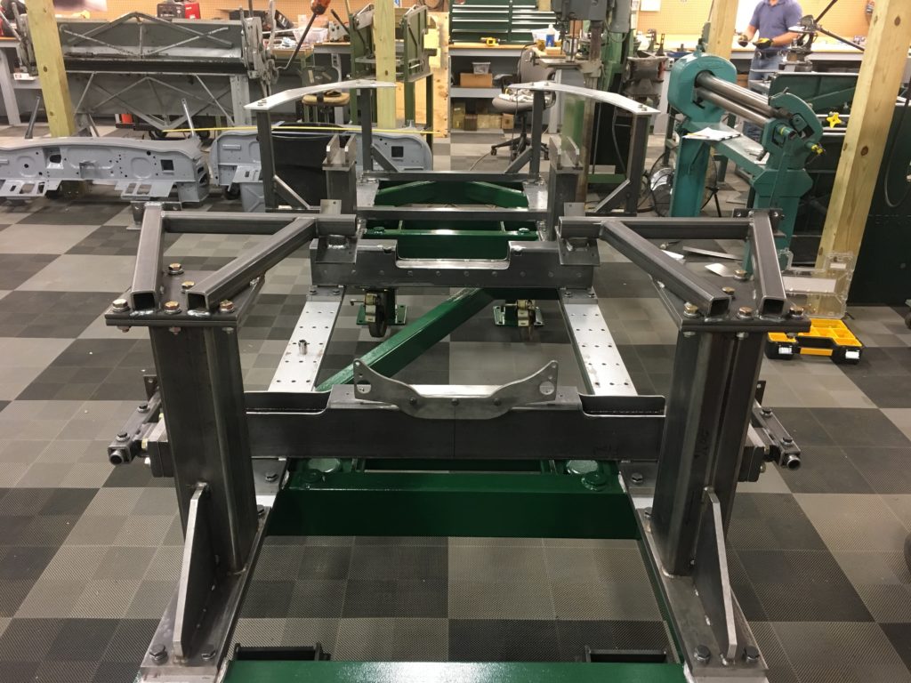
- This 1961 OTS was used as a guide for the initial construction of the front “towers” as we call them. They are also precisely 90-degrees to the table itself.
-
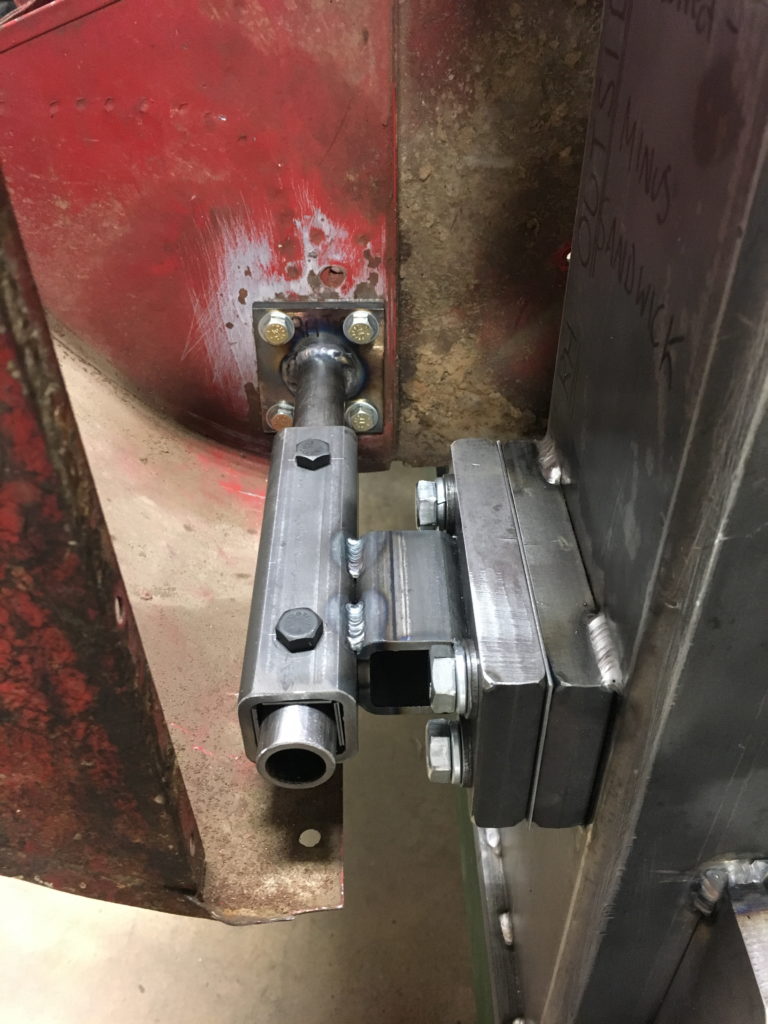
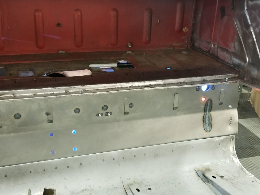
- This is the attachment for the lower, outer engine frame rail mounting pads. As you can see, this assembly is adjustable with shims in all dimensions. There is one combination of shims that is documented as absolutely correct and symettrical with the other side. But other combinations can be used to mate up with original shells, which are not quite as precise as our new jigs…

-
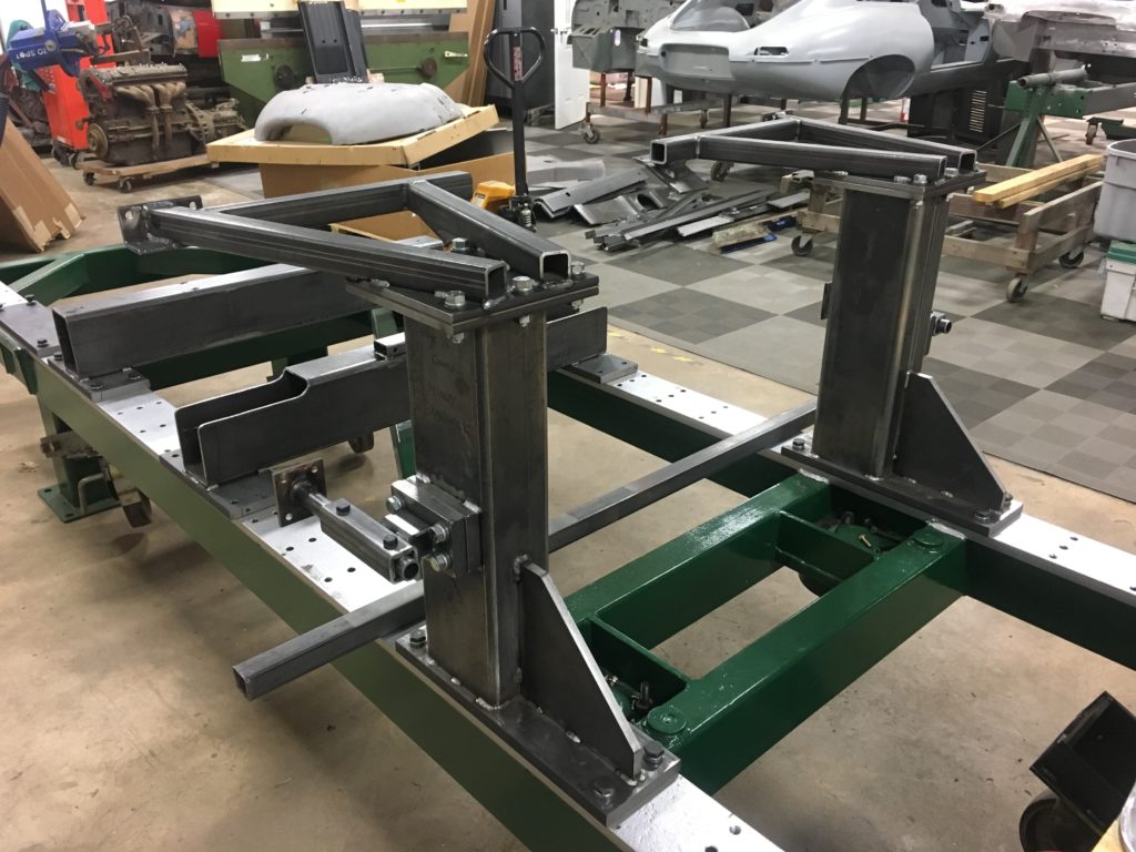
- Here is another shot of the front towers. Here, a piece of heavy wall tubing is laid across the table surface and is being used to check the precision of the upper frame rail mounting pads directly above – we used squares, plumb-bobs – you name it to triple-check every dimension and adjust it by changing the shim packs.

-

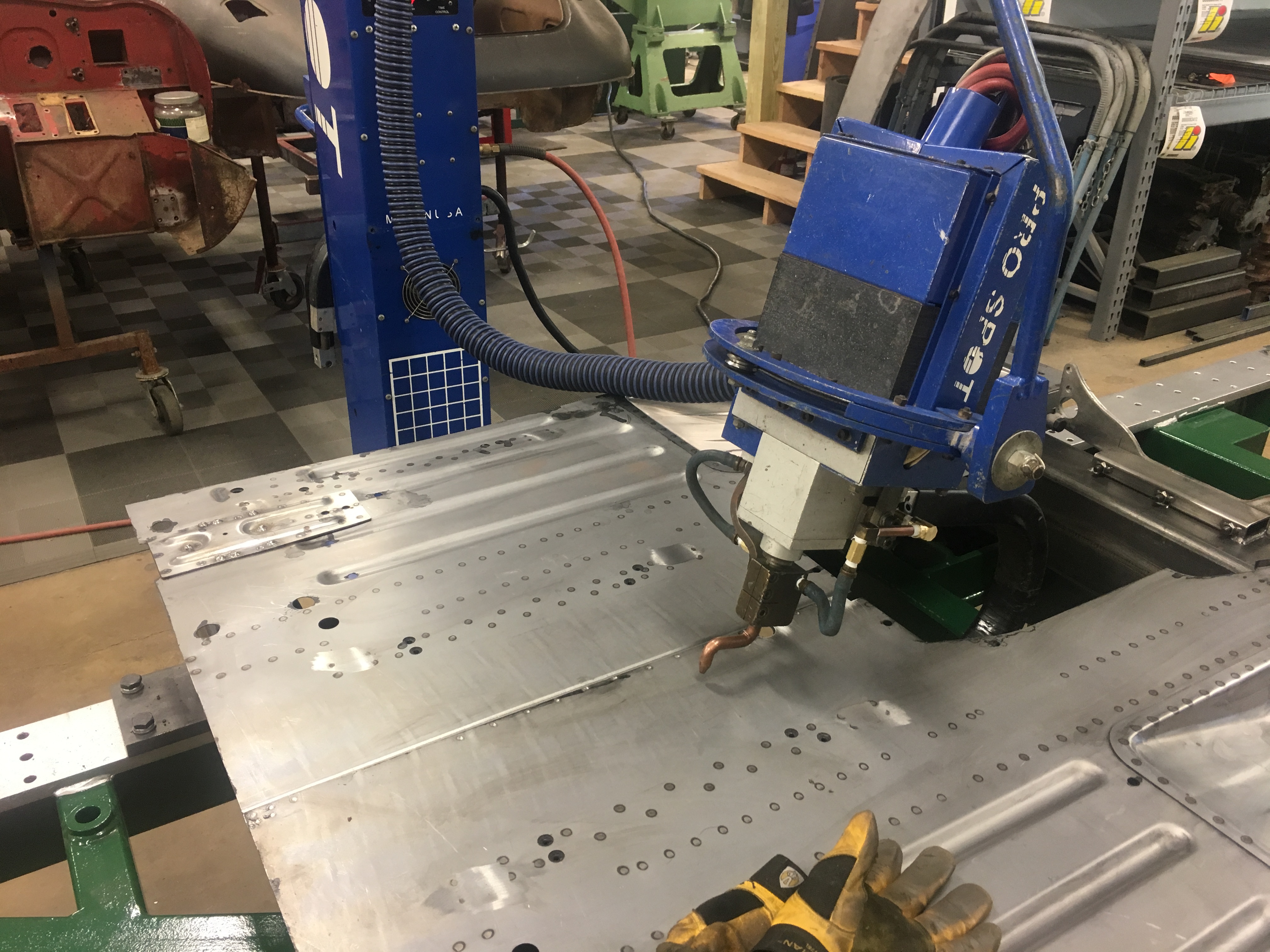
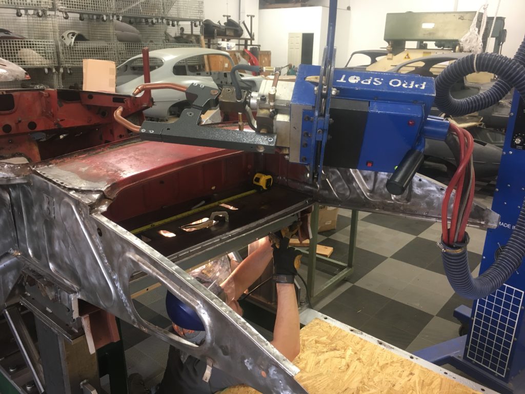
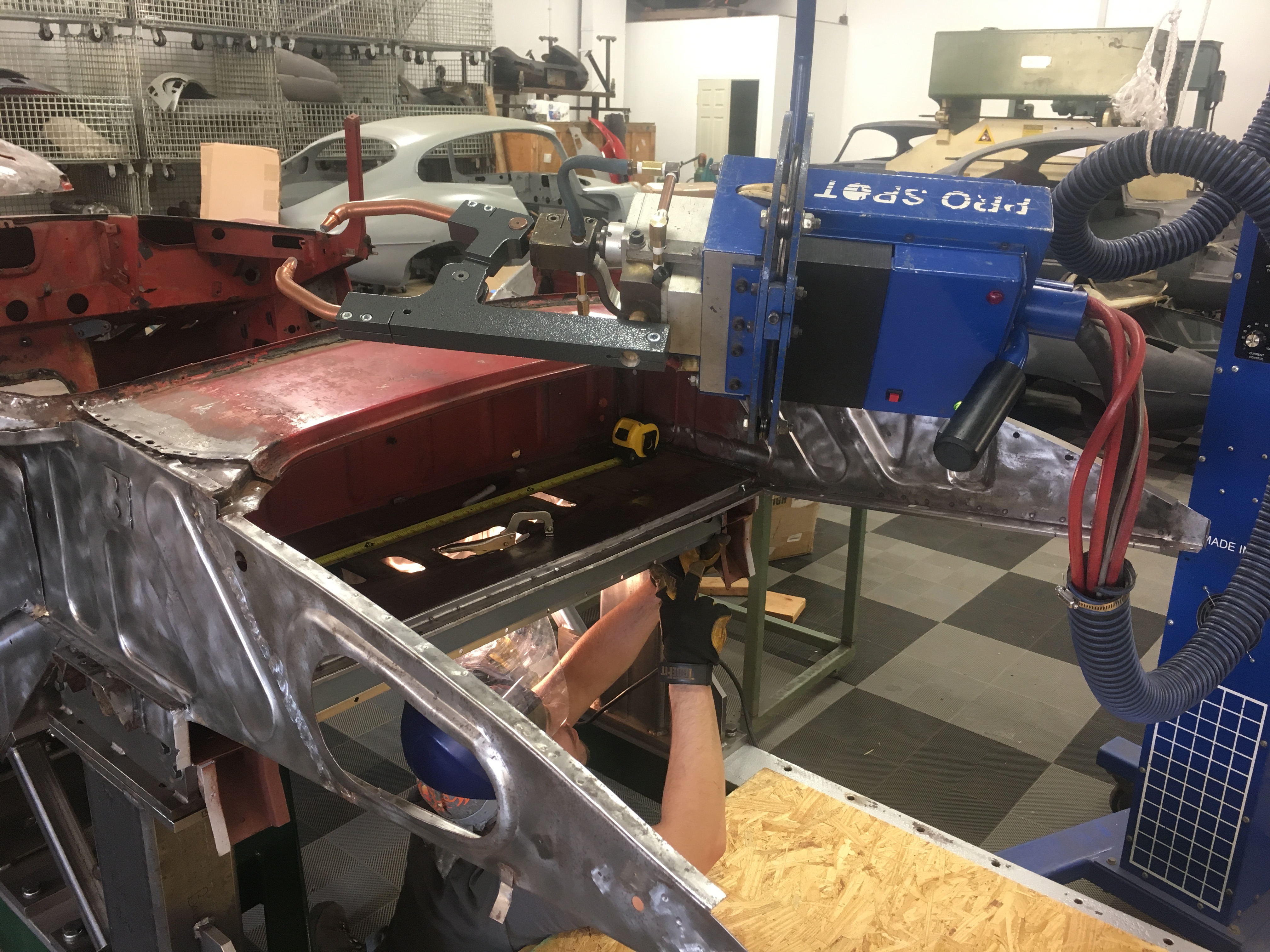
- In this shot, we are using a water-cooled spot-welder to build up our firt floor assembly in the jigs. During that process, we made some design changes, as you need to be able to get around your jigs to do the work!
-
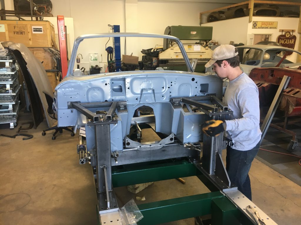
- Here, Brent is fitting up a restored original forward bulkhead assembly to the floor assembly. One reason I eventually decided to just post photos of the new jigs is that if I’m not willing to show them, I can never blog again – there is no way around showing them!

-
- Here is a good shot of the comeplet front tower assembly being used to PERFECTLY align the forward bulkhead with the floors…

-
- …but only temporarily… Now it is back off and we are spot-welding the inner sills to the floors.
-
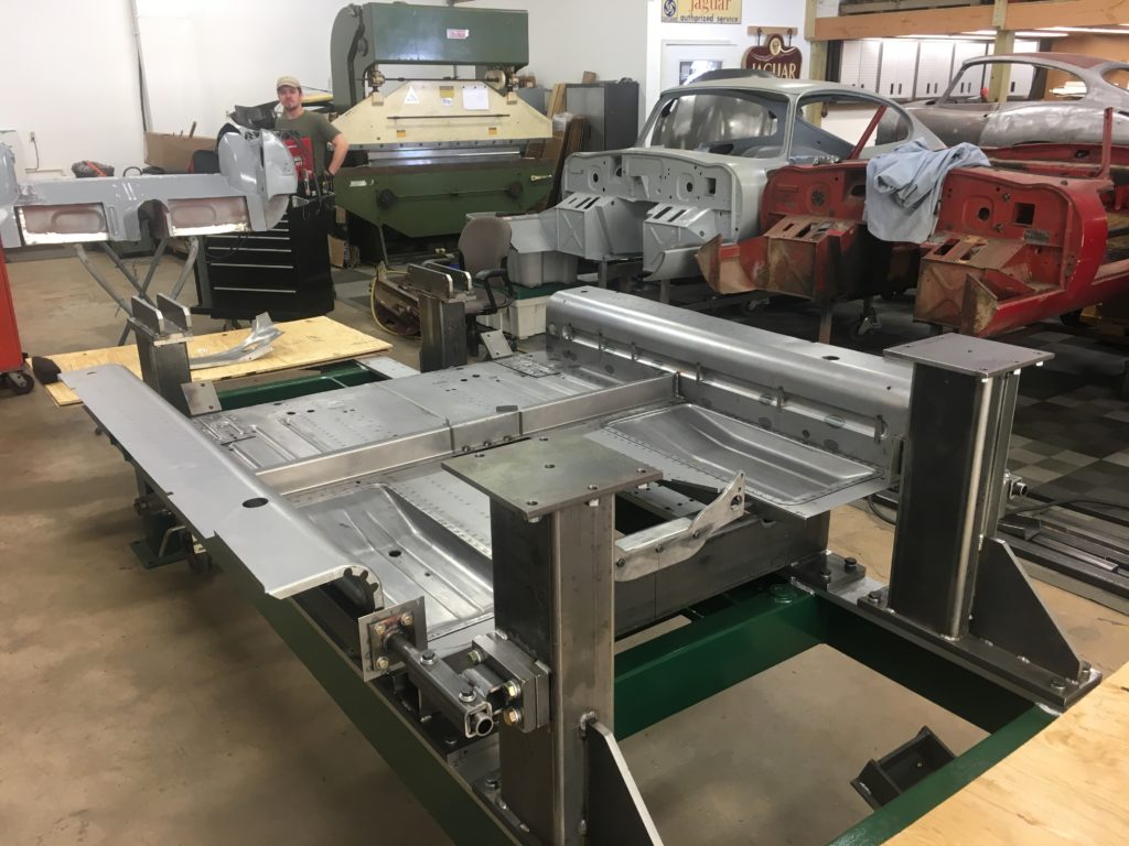
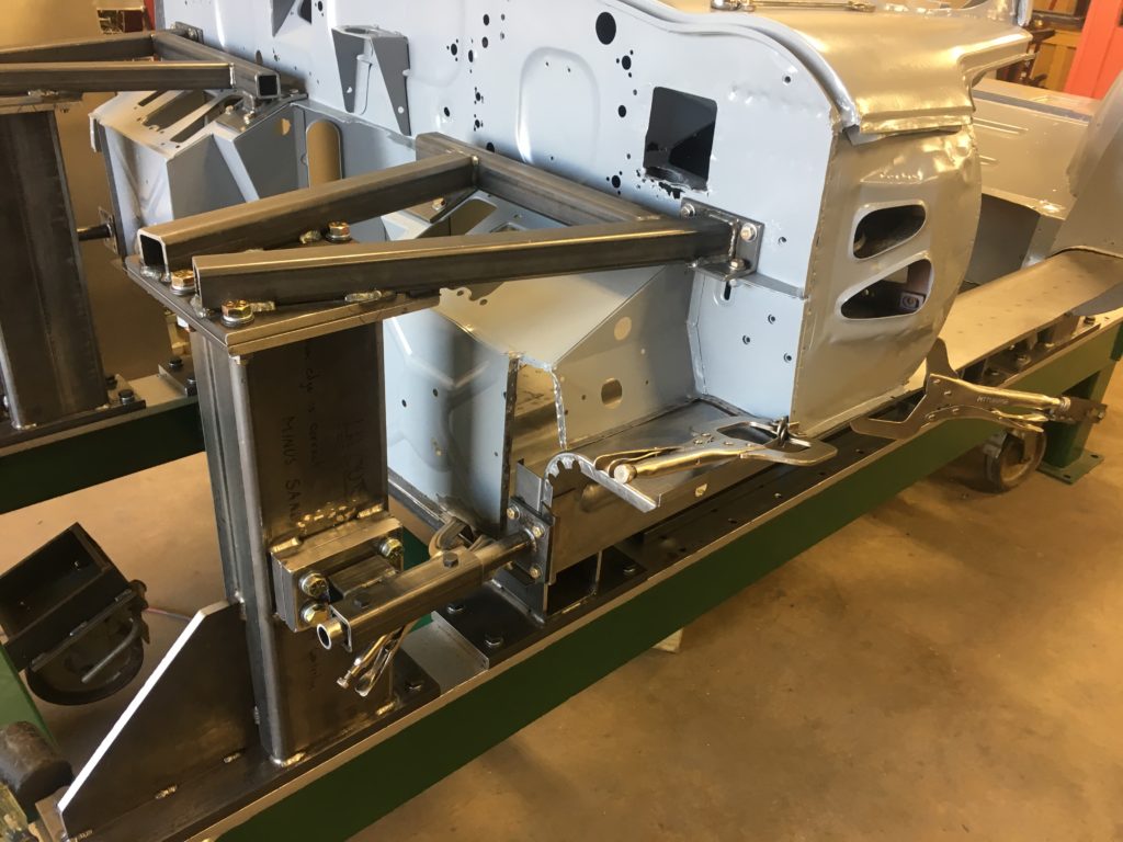
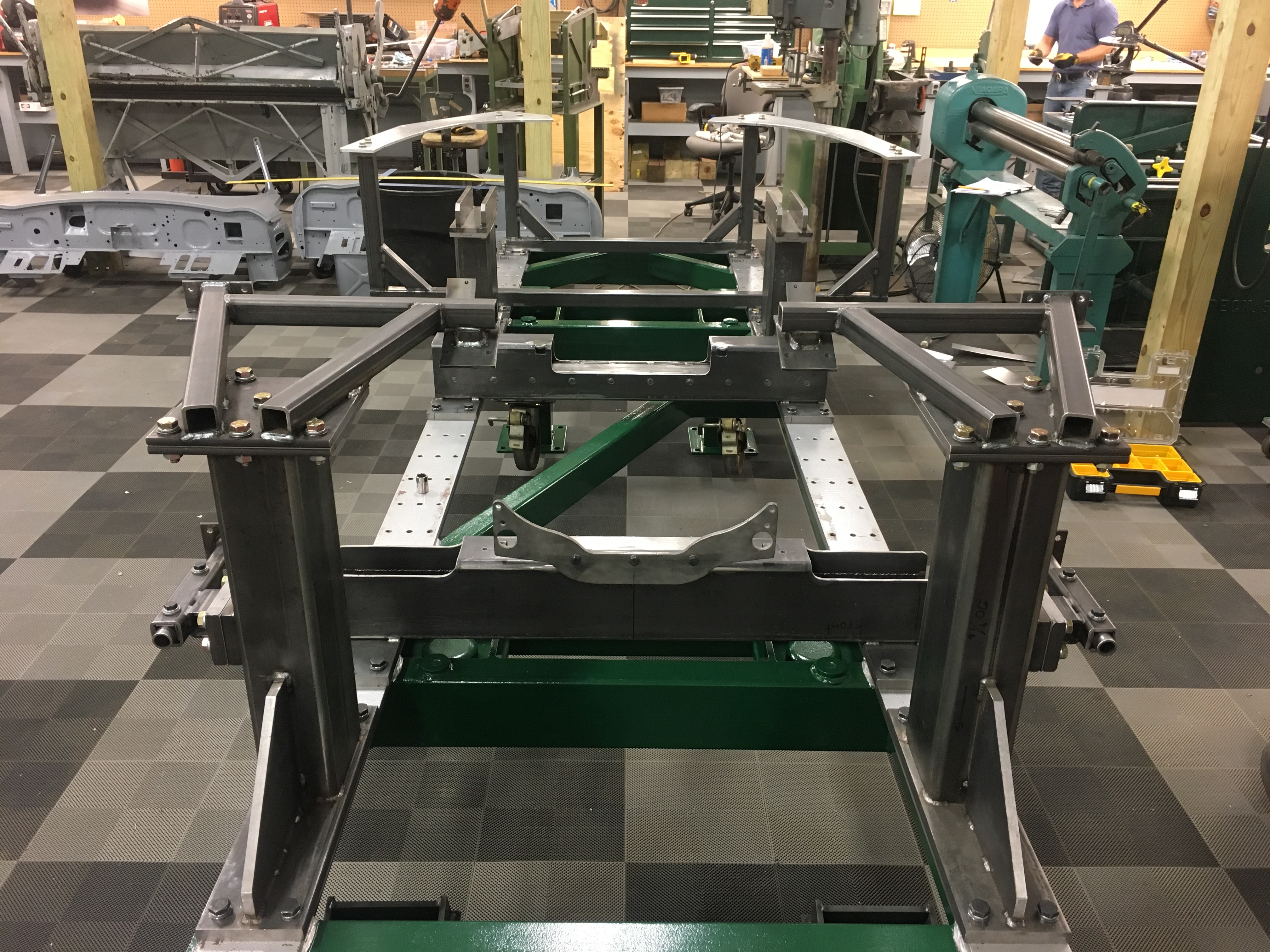
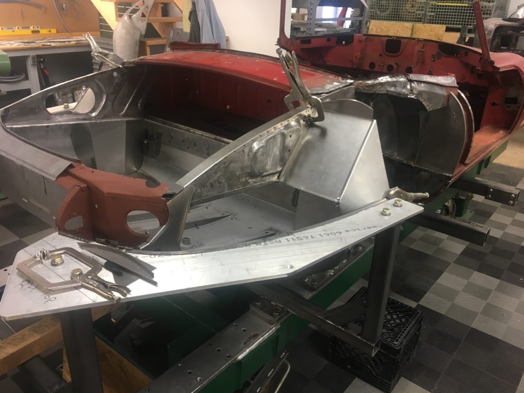
- Here. the floors and inner sills are all welded together – and I just can’t stress or say this enough – in ABSOLUTE 100% PERFECT ALIGNMENT! We have also added the outer sill tubing and engine frame plates for one of our hidden subframes.

-
- Next,we have used the rear towers to mate up this original rear bulkhead assembly to the new floors and inner sills. The rear towers are less elaborate, but were much more difficult to fabricate than the fronts. Getting the dimensions right for the rear towers almost drove me completely insane last Spring – and made me wonder if there are ANY straight E-Type shells left in existence!

-

- This time, the forward bulkhead is going on for good.
-

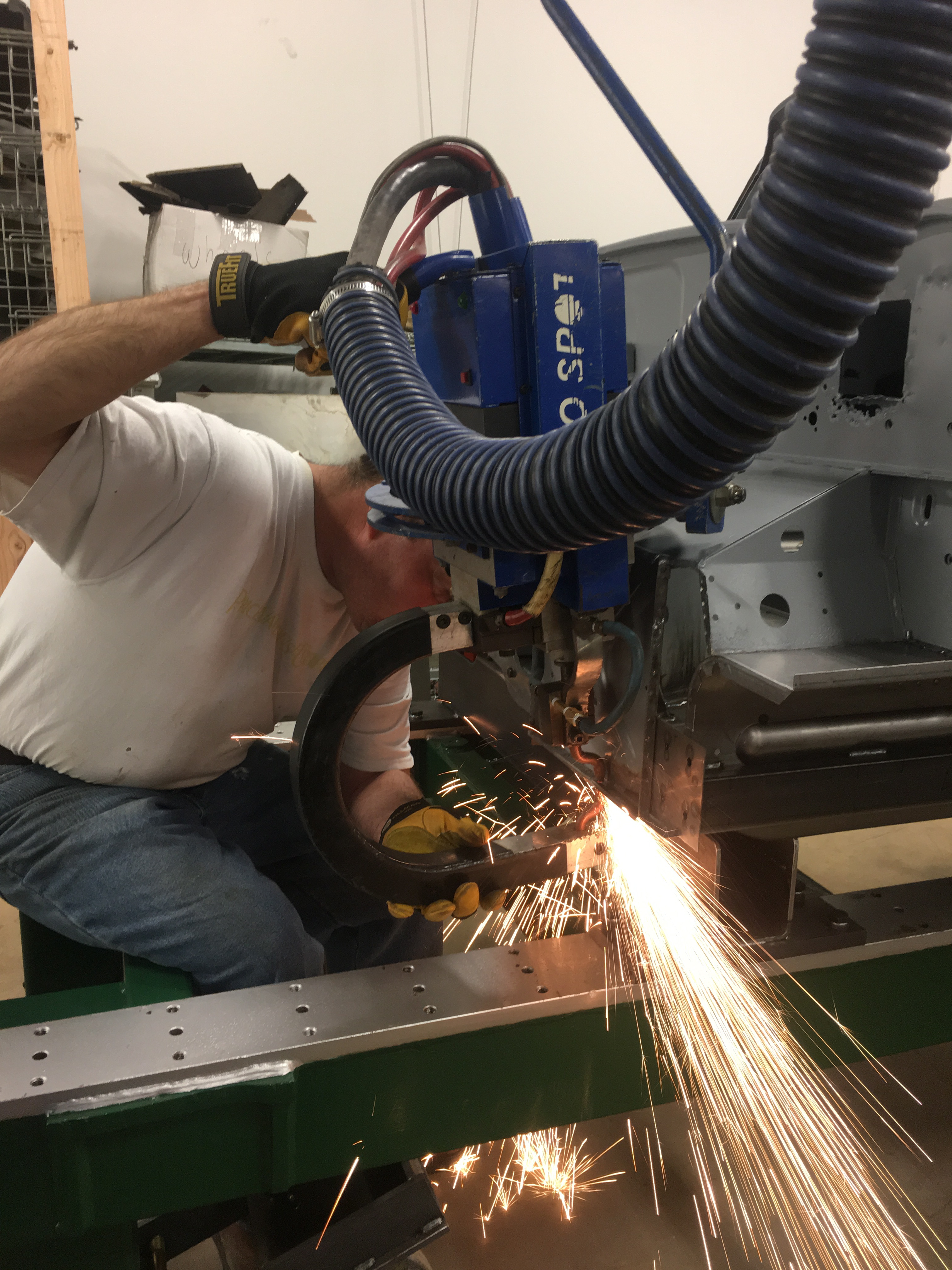
- Here is yours truly using the spot-welder. YOu have to take a “burst” of photos to get this shot – this was one of about 50 photos taken in one second – it doesn’t last long!
-
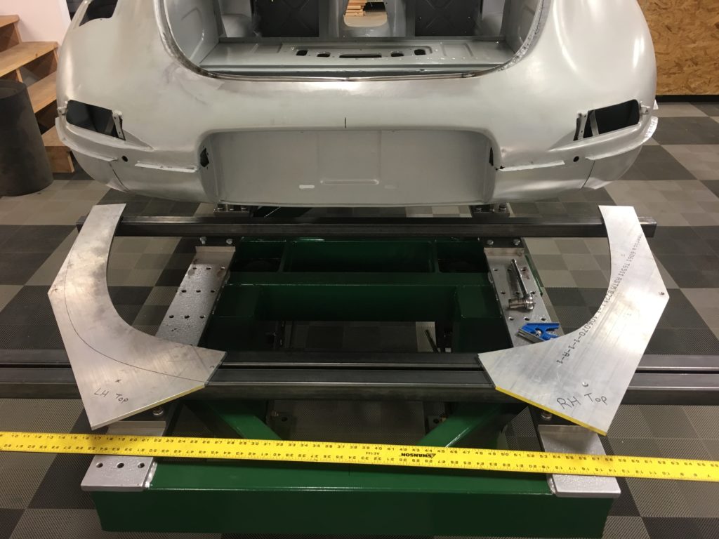
- Once we completed the partial low-drag replica shell, we got back to work on more jigs… Here, the tail jigs are being built.

-
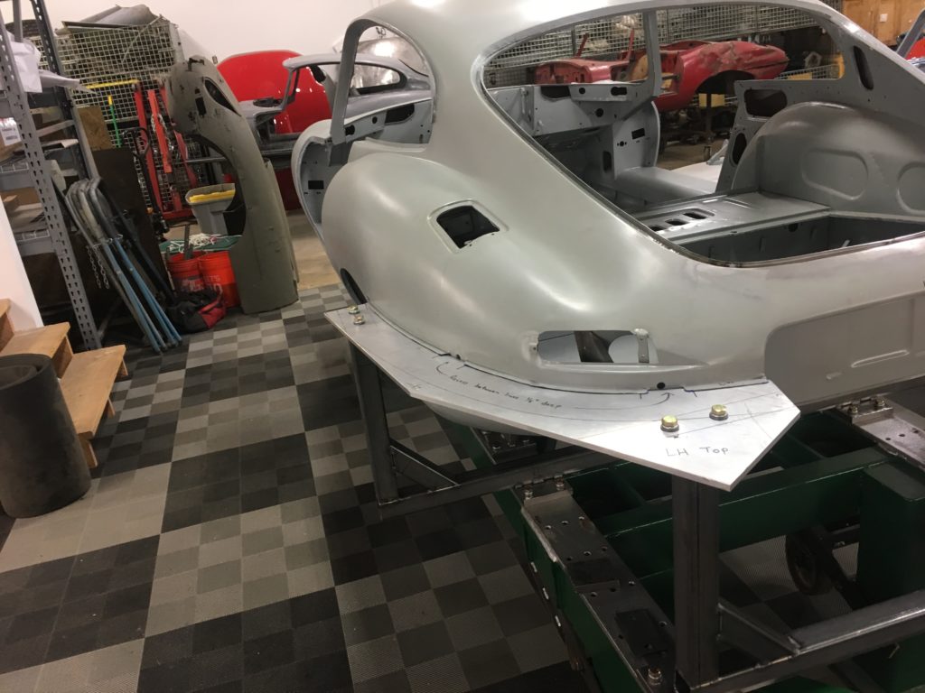
- These plates were another research experiment… We had 8 E-type shells last Summer, and this shape was not the same on ANY of them! I was finally able to deduce what was correct, though – and that was half of the battle with this project. I’m not sure that very many other people could even do it – you need ALOT of E-Types around to get the job done!
-
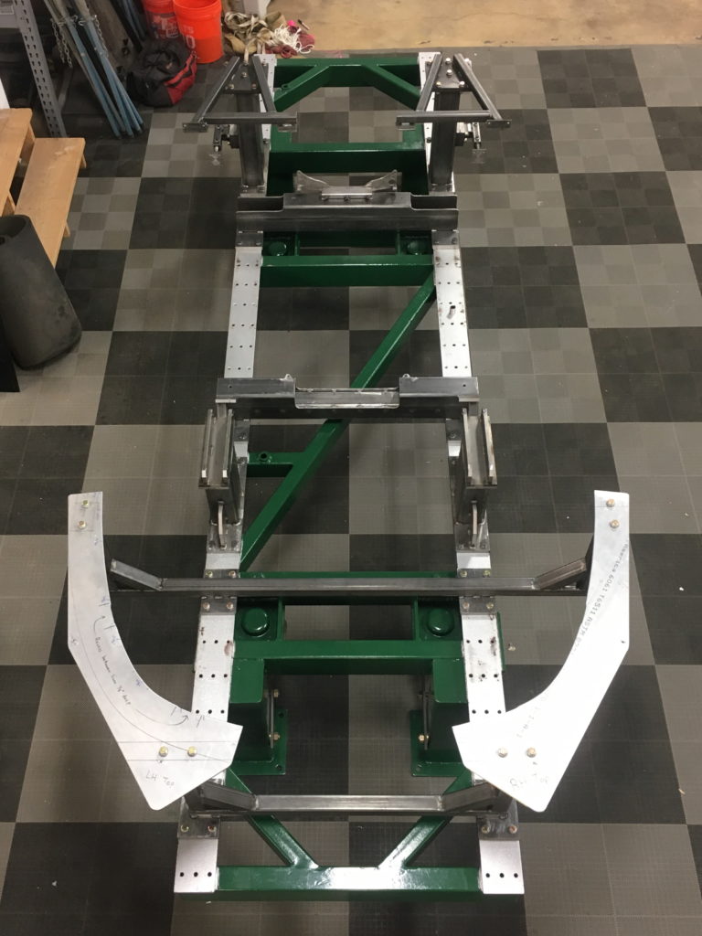
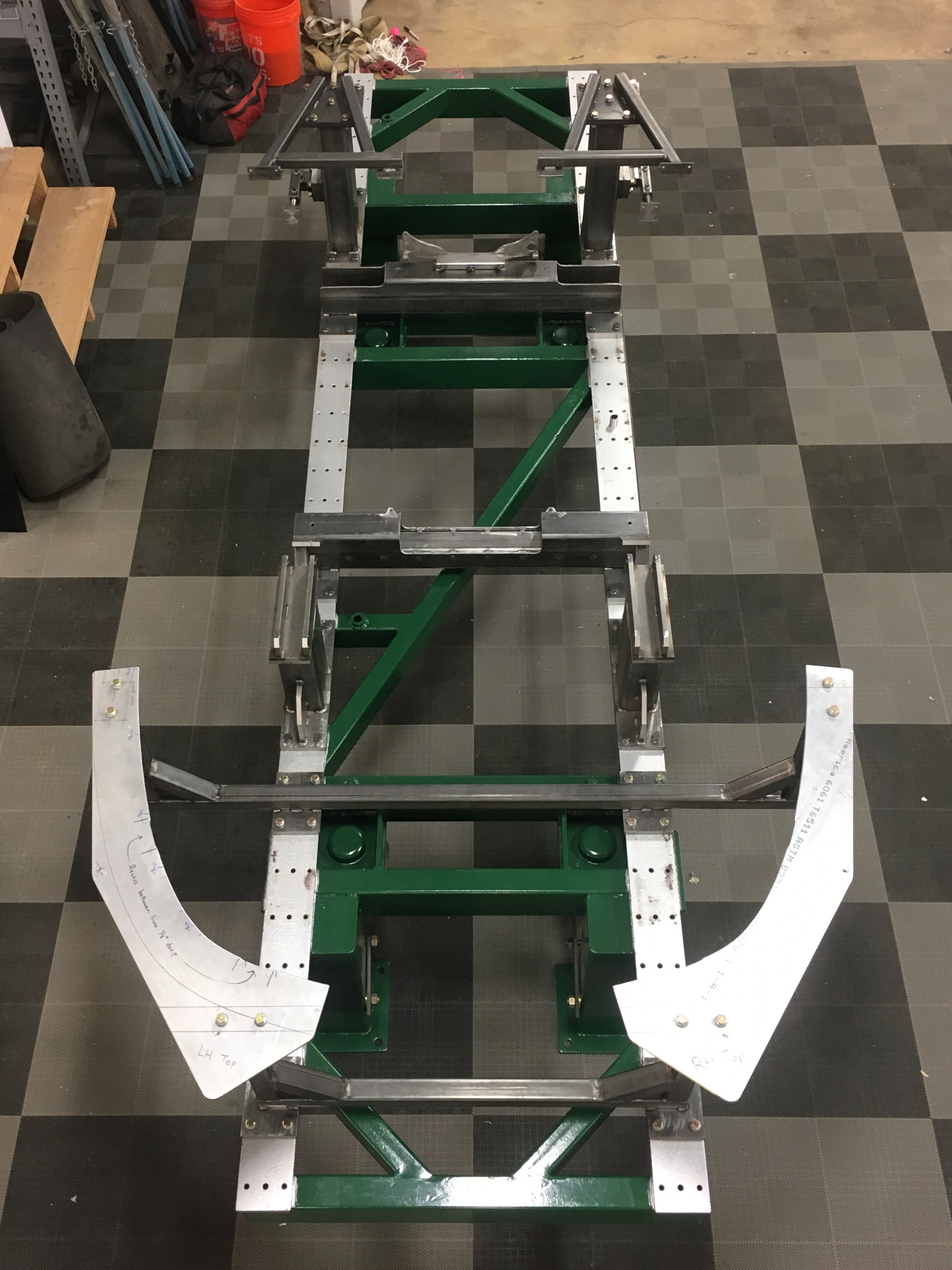
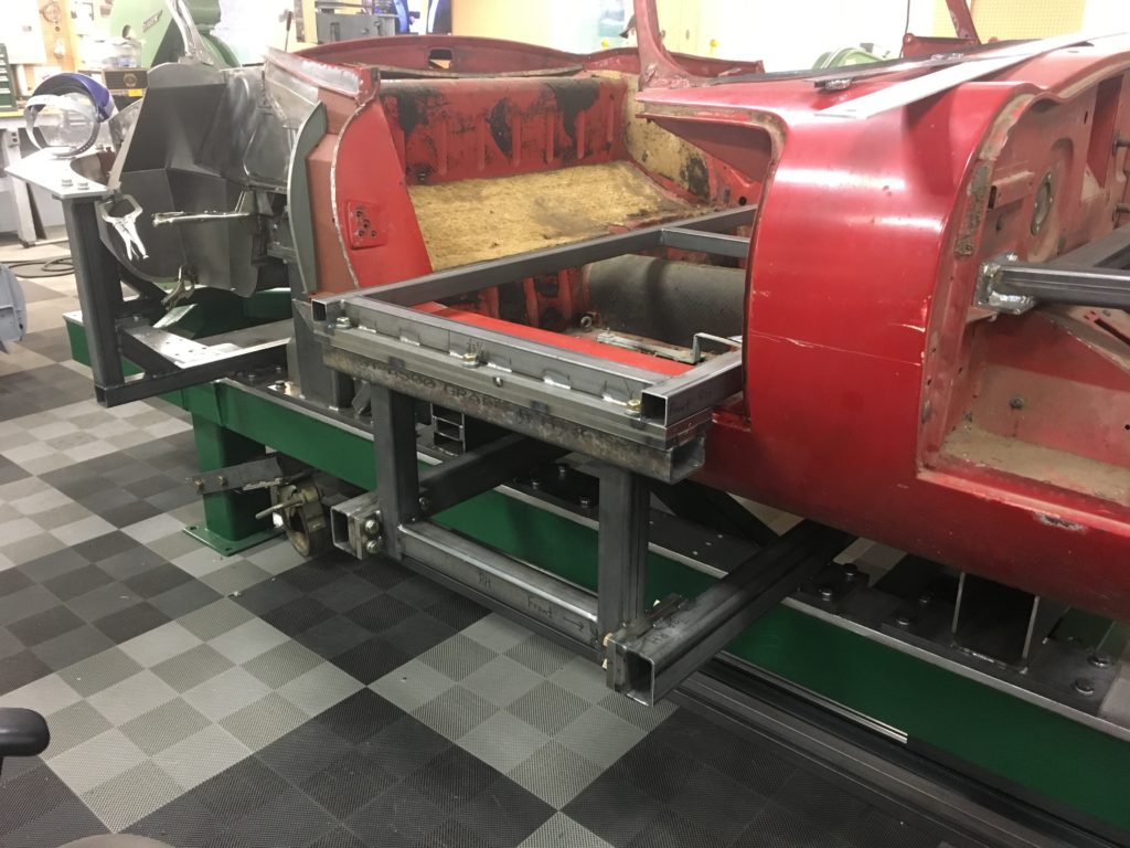
- Here is the semi-completed chassis table as of last Summer.
-

- I was very excited once we reached this point – I knew that we REALLY had something great on our hands now!
-
- Now I had what I had been dreaming of for years – a ROCK-SOLID jig that was absolutely perfect, that could be built to as “THE LAW” – without all the measuring we used to suffer through on every build…
-
- So we started using it! We mounted the ’61 OTS shell back into it and started the reconstruction of the wrecked tail. The shell mounted up into thre of the 4 towers beautifully, and then was way off on the RH rear tower. So we simply used jacks and levers to twist what was left of the body into shape until it WOULD fit into that tower, then mounted it and moved forward!
-
- That’s me under there, plug-welding a support piece in just in front of the forward boot wall. Despite a mountain of spot-welding attachments, you just can’t reach everywhere!

-
- THIS is what I wanted! We are simply now building to this jig, knowing that it is correct! And I soon began to realize that we could never have repaired this shell correctly without it!

-
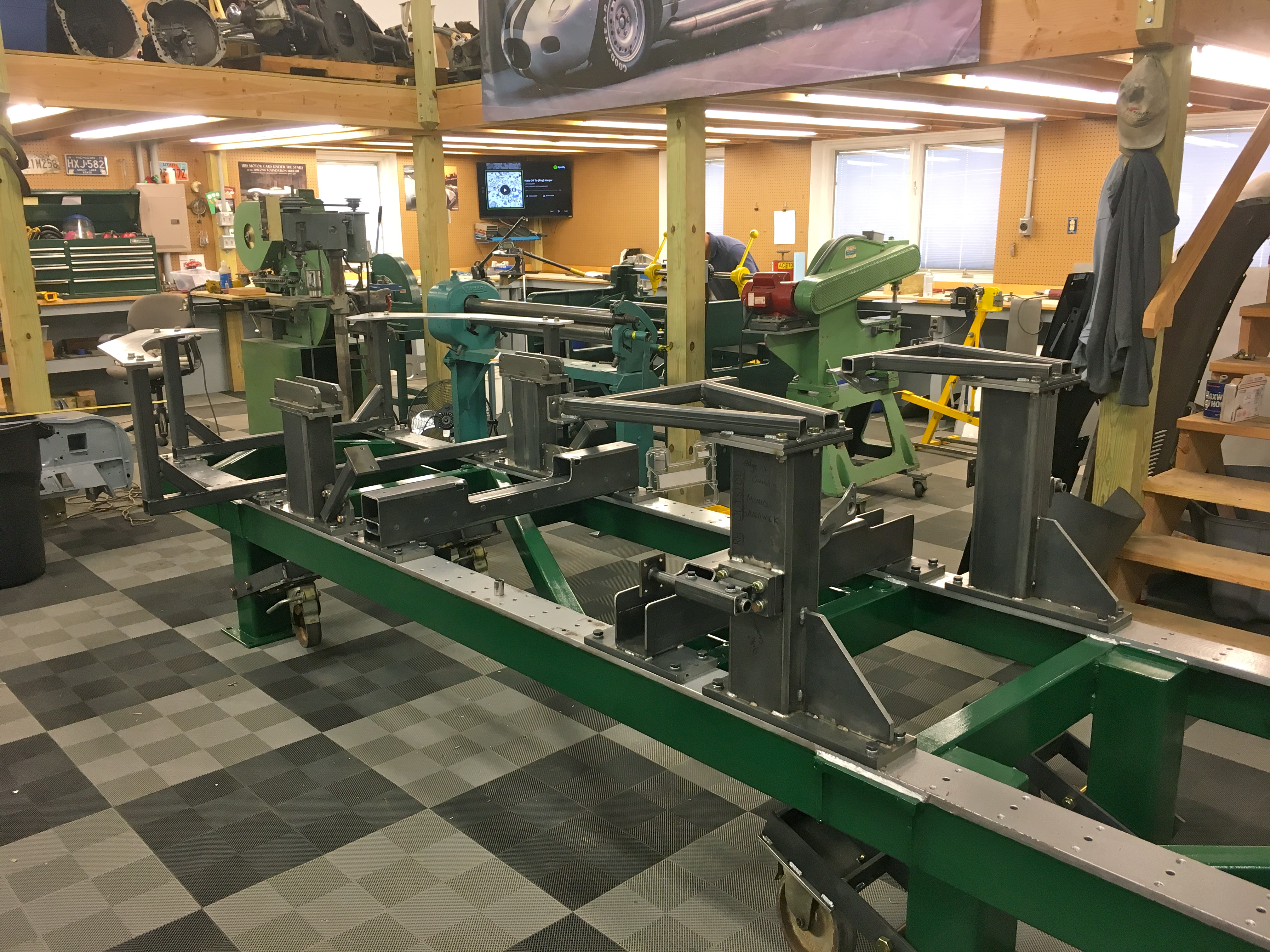
- Then came the insanity… This is the beginning of “the cockpit jigs” – not necessarily needed to restore shells, but absolutely necessary to build them from scratch, which is our ultimate goal.

-
- Here, we are building the main cockpit jig “base” on a surface plate at Steve’s shop. Note the clamps and milled angles to keep everything perfectly square. See that little piece of paper between the jig and the angle bracket where it is vice-gripped? That is a .002″ adjustment in alignment – YES – we were THAT precise throughout the entire build!

-
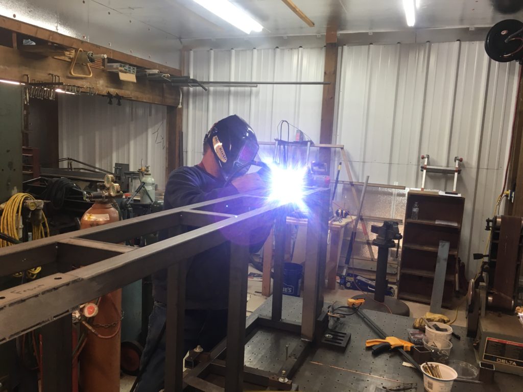
- A shot of Steve TIG welding the cockpit frame in his shop.

-
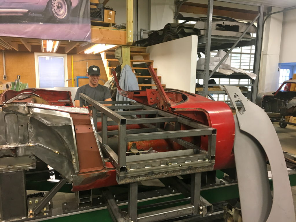
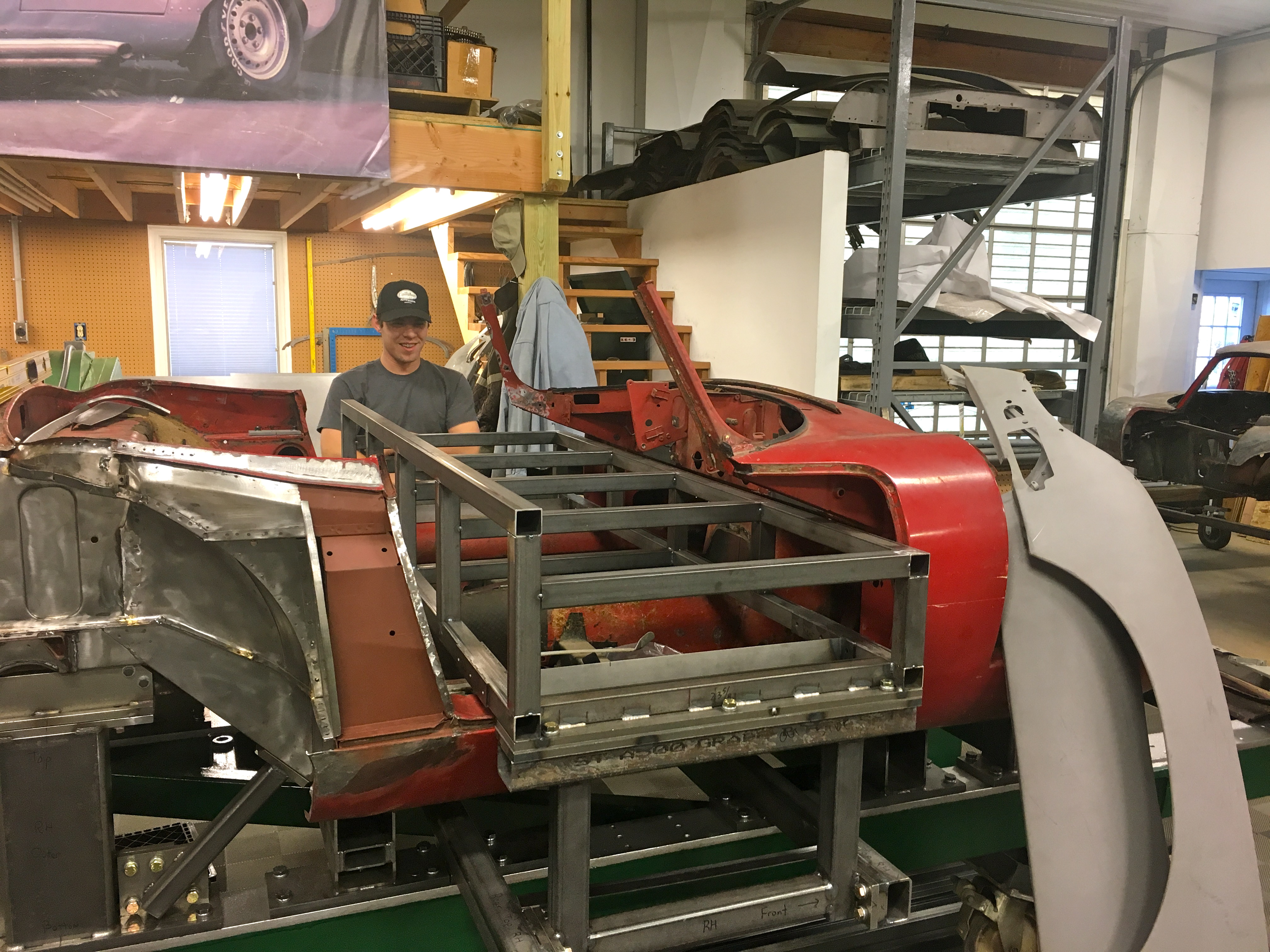
- Back at the shop on a Friday afternoon last Fall, brent is smiling as we mounted the cockpit frame into the chassis table for the first time. He is actually laughing, as we were commenting that this doesn’t actually DO anything itself – we still have to build jigs onto it! And the joke is that it had taken Steve and I over a month to build all of this cockpit stuff so far…
-
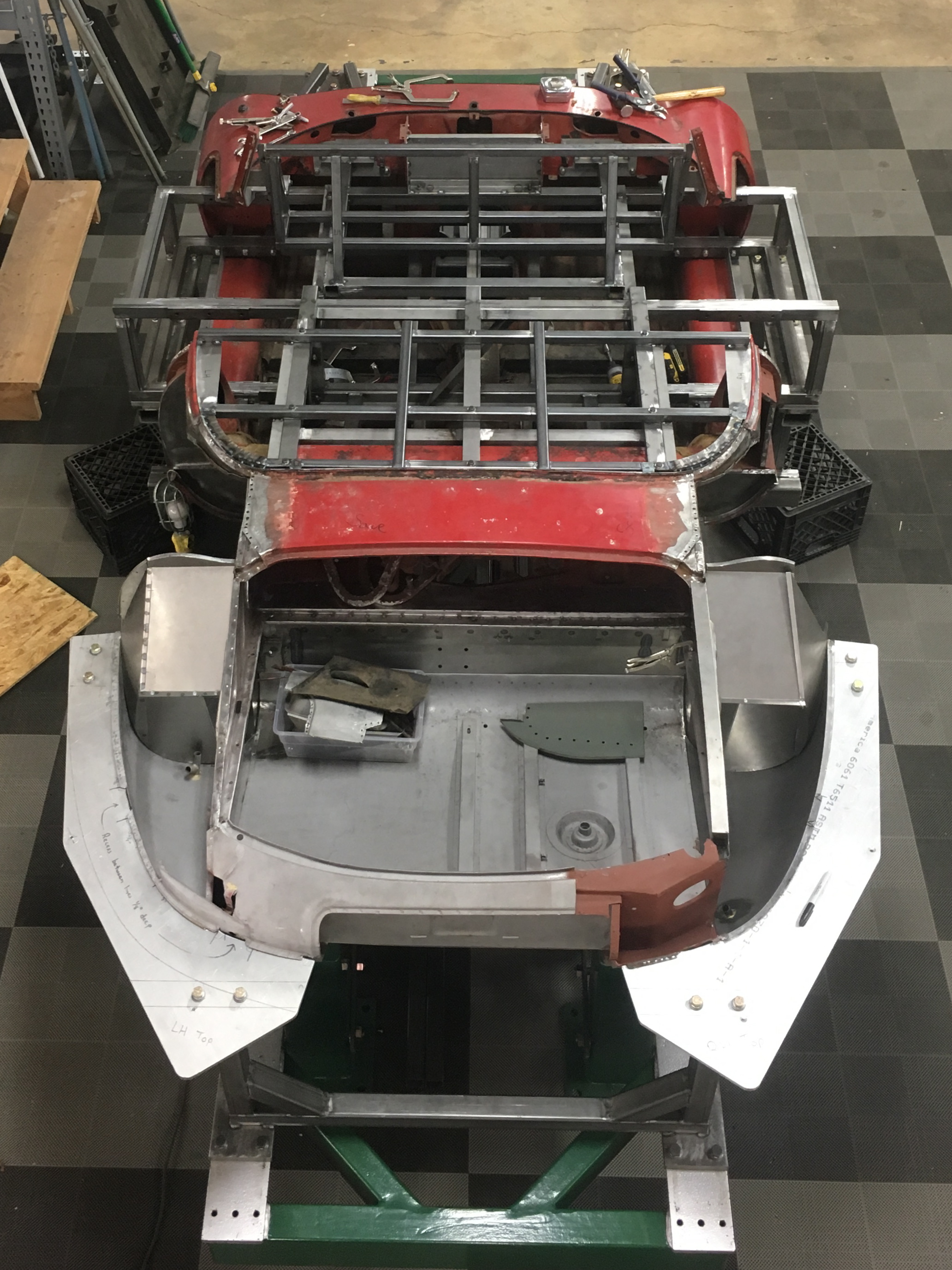
- But then I went nuts adding to that frame and picking up every point that I felt was necessary to properly align and build the cockpit. One nice thing about the table itself is that you can easily drop down with squares and straight edges and determine that even though the tail is incomplete, the cockpit is perfectly symettrical and can be built to as a master – although in building, there is still a heavy use of shims, and they will be adjusted once this ’61 shell is out to make them perfectly symettrical – as Jaguar was a littel sloppy here and there…

-

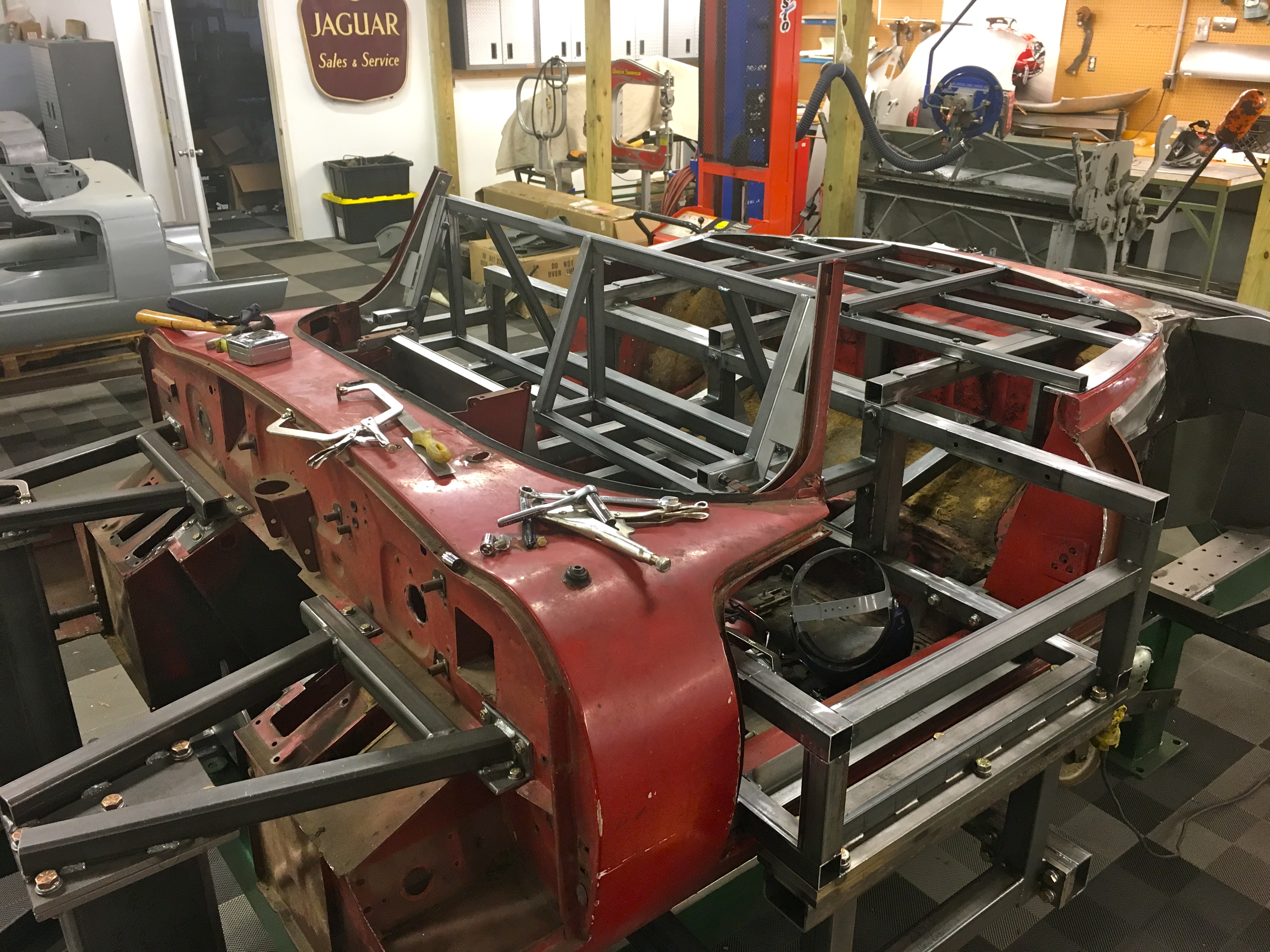
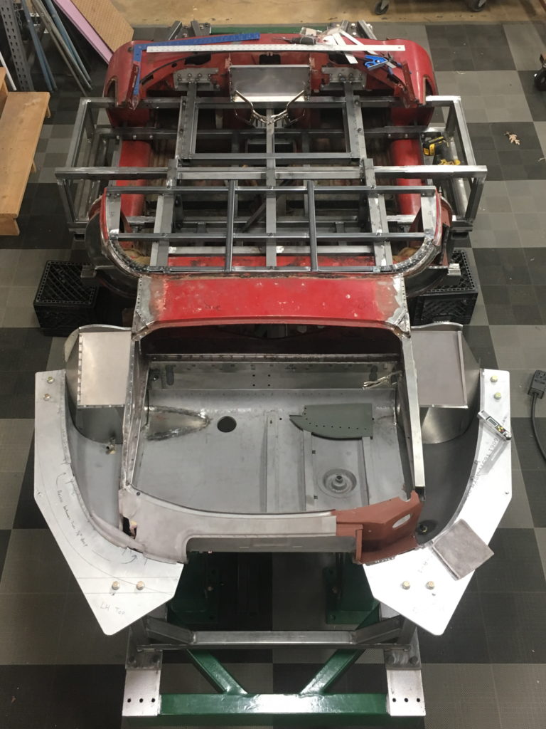
- This is a shot of the completed cockpit jigs – now with the windscreen post jigs built. The windscreen posts were one of my biggest concerns – they are ALWAYS out of whack on roadsters, and again, I wanted a true master jig versus trying to align them with a windshield and straight edges, etc.
-

- Another shot of the completed jigs. If you want your E-Type bocy shell to be rebuilt PERFECTLY, this is the place…