Once the issues with the rear wings were all resolved, it was OK to go ahead and put in the floors and inner sills.
-

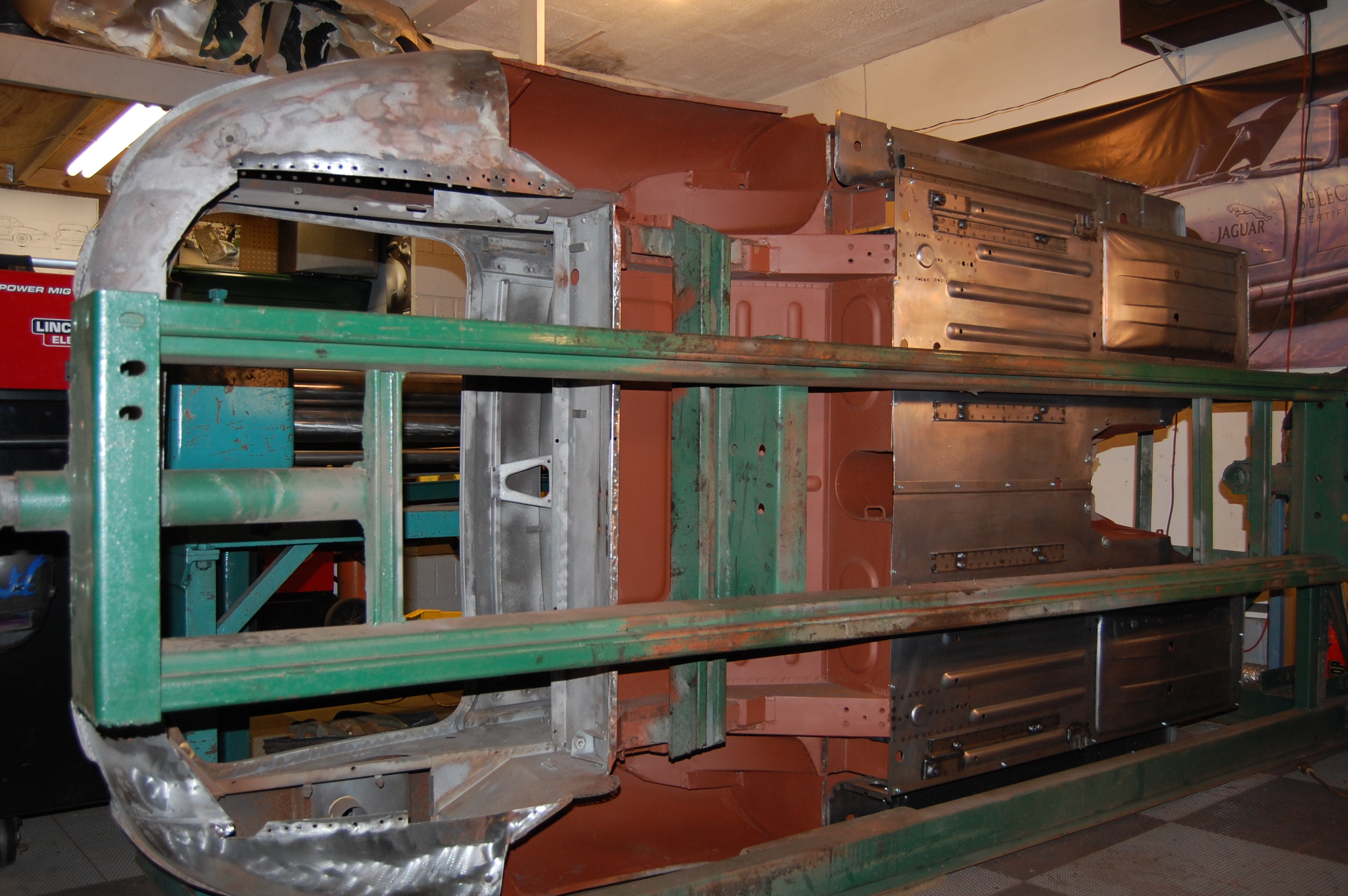
- We start by fitting the floors to the shell and the jig.
-
- This looks simple, and is I guess, but it’s very time consuming as you go around the entire perimeter and make small adjustments to get the correct fit. 1/16″ here and there can make a big difference in the end product!

-
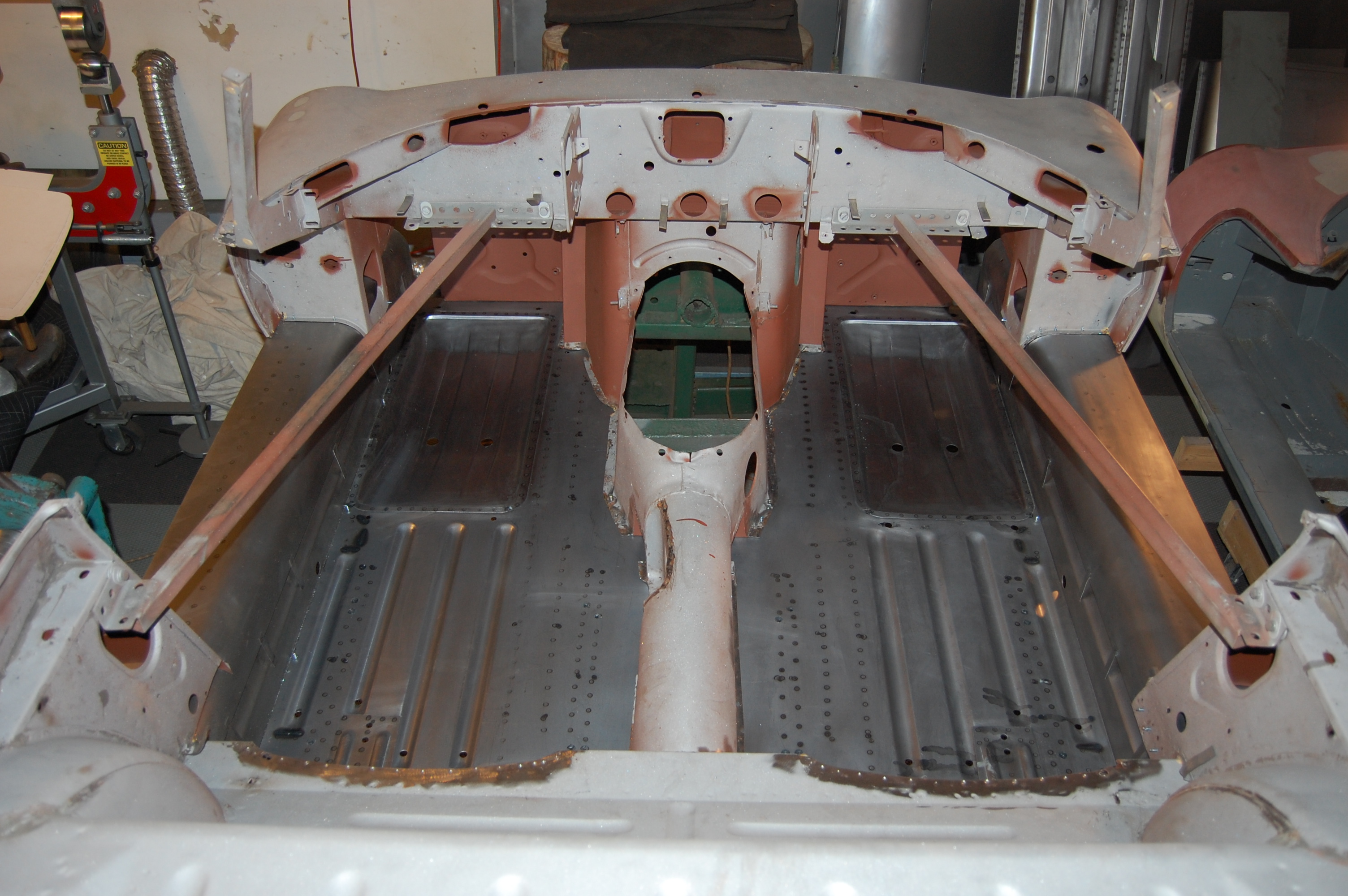
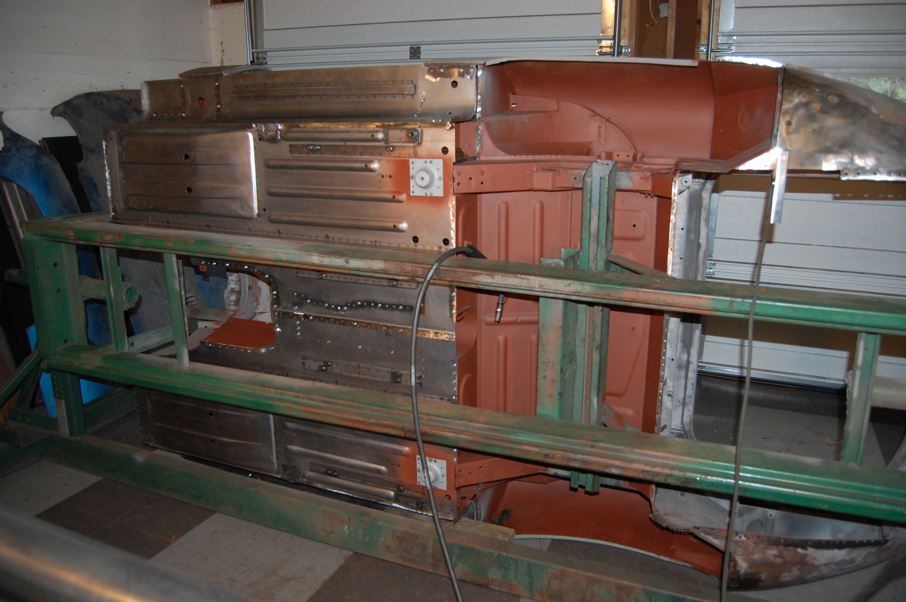
- Here, both sides have been fitted – you really have to do the floors and inner sills at the same time.
-
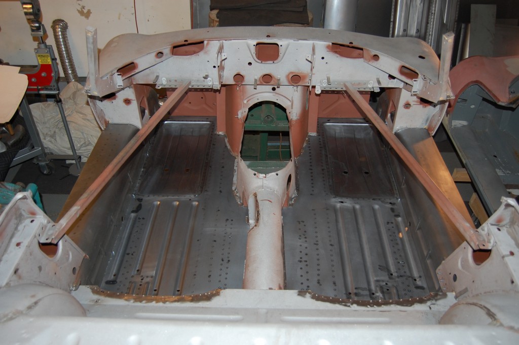
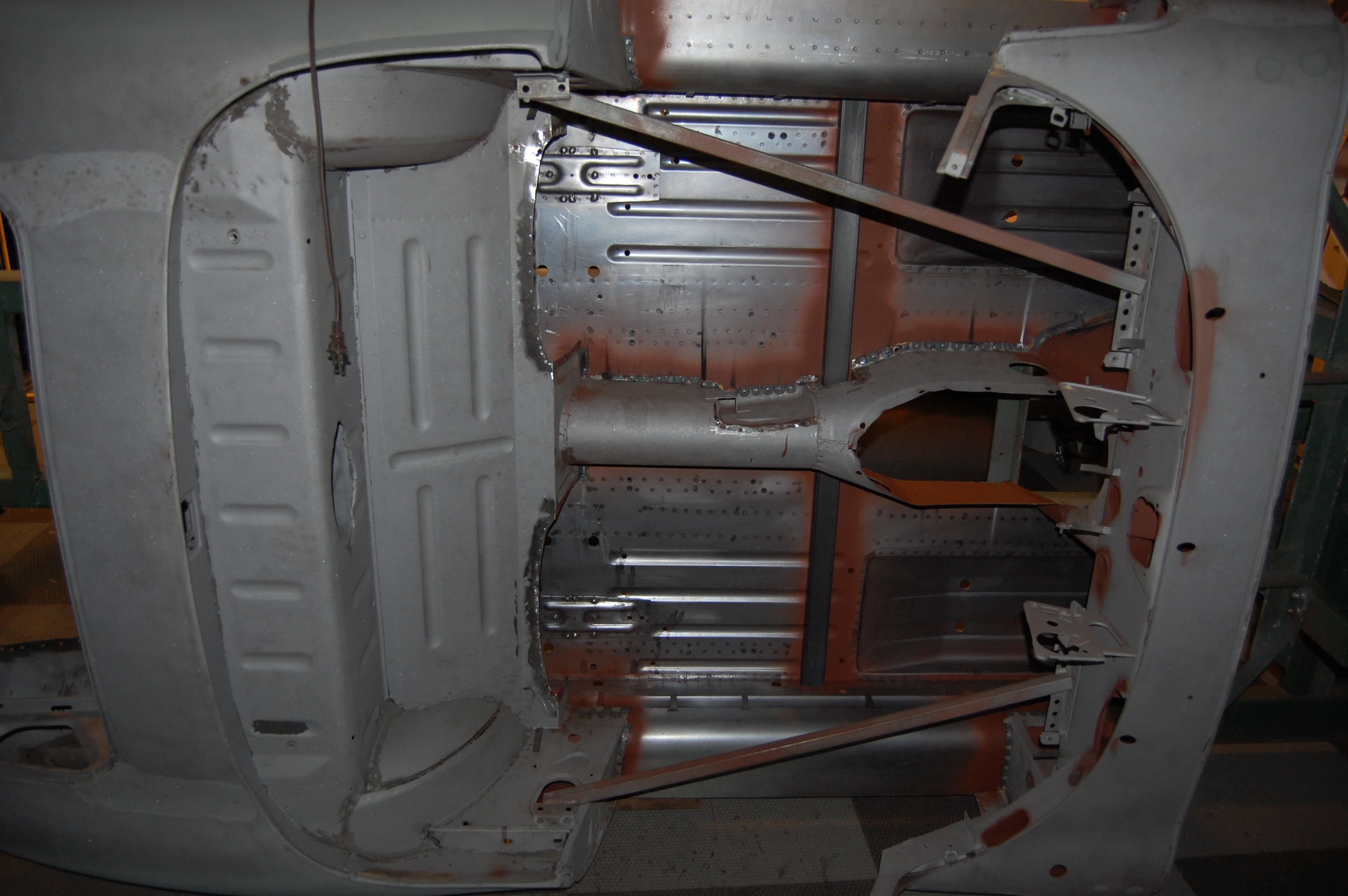
- All fitted up. If you look closely, you can see that the forward tunnel section on the RH side is canted outward at the bottom. This is known, and will be remedied as the floors are welded in – there no need to force it into place at this stage.
-
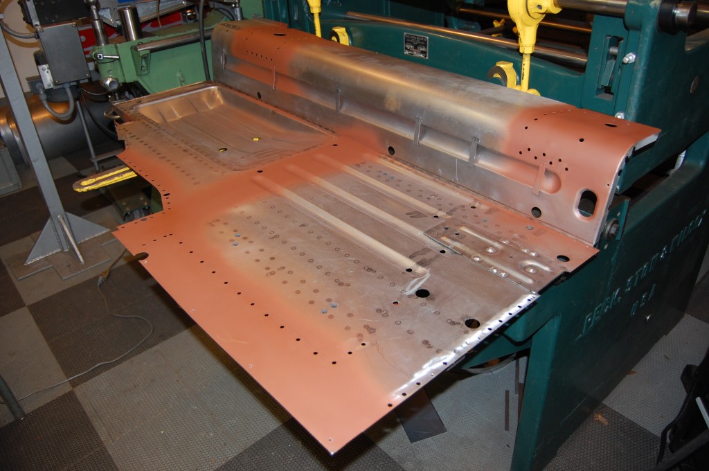
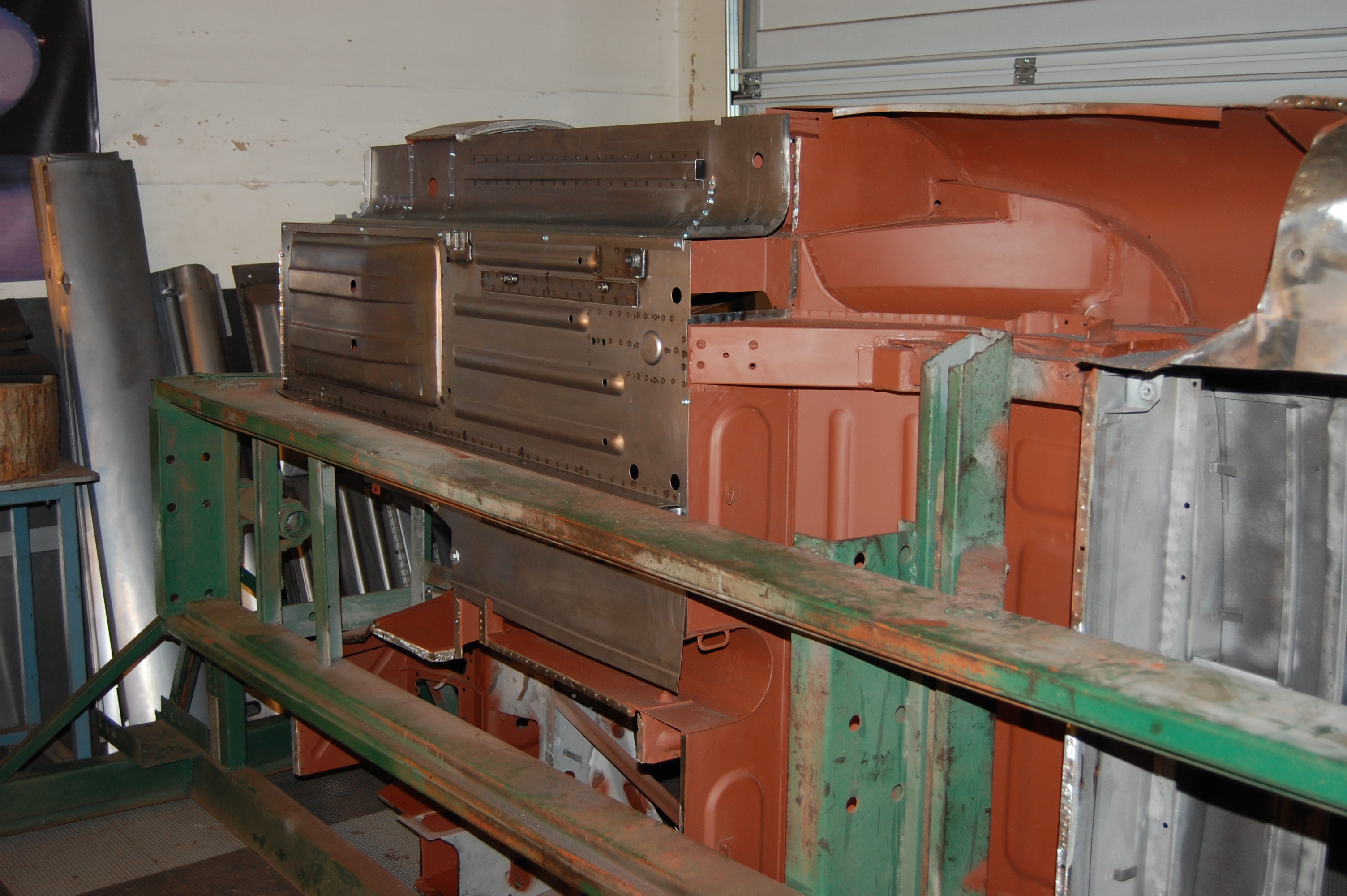
- Next, everything comes out, and the inner sills are fitted to the floors on a bench in the same alignment as they were fitted to the shell, using holes, marks, etc. We also throw some red oxide on areas that will be boxed in.

-
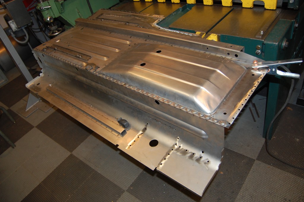
- The inner sill is drilled, and plug-welded to the floors. You can use a spot-welder here, but it better be INDUSTRIAL strength – I’m talking something that is 6 feet high, water cooled, etc. The usual tong-style air cooled units will flex too much if the tongs will reach around the inner sill, and you don’t get the clamping pressure you need for a safe weld. Remember, along the recessed footwell, it’s THREE layers now – not two. We don’t mess around here, we plug-weld it.

-

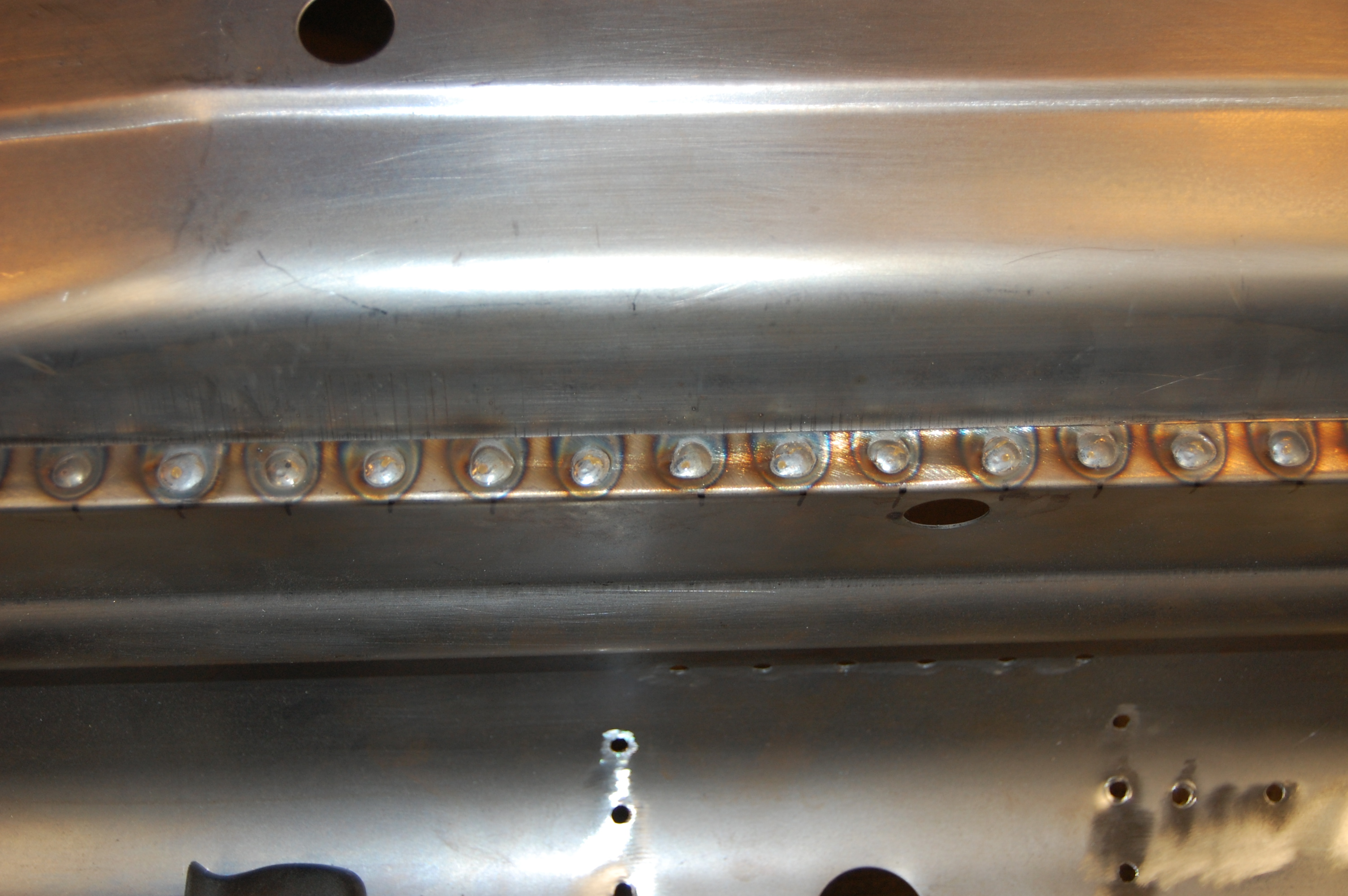
- These aren’t going anywhere!
-
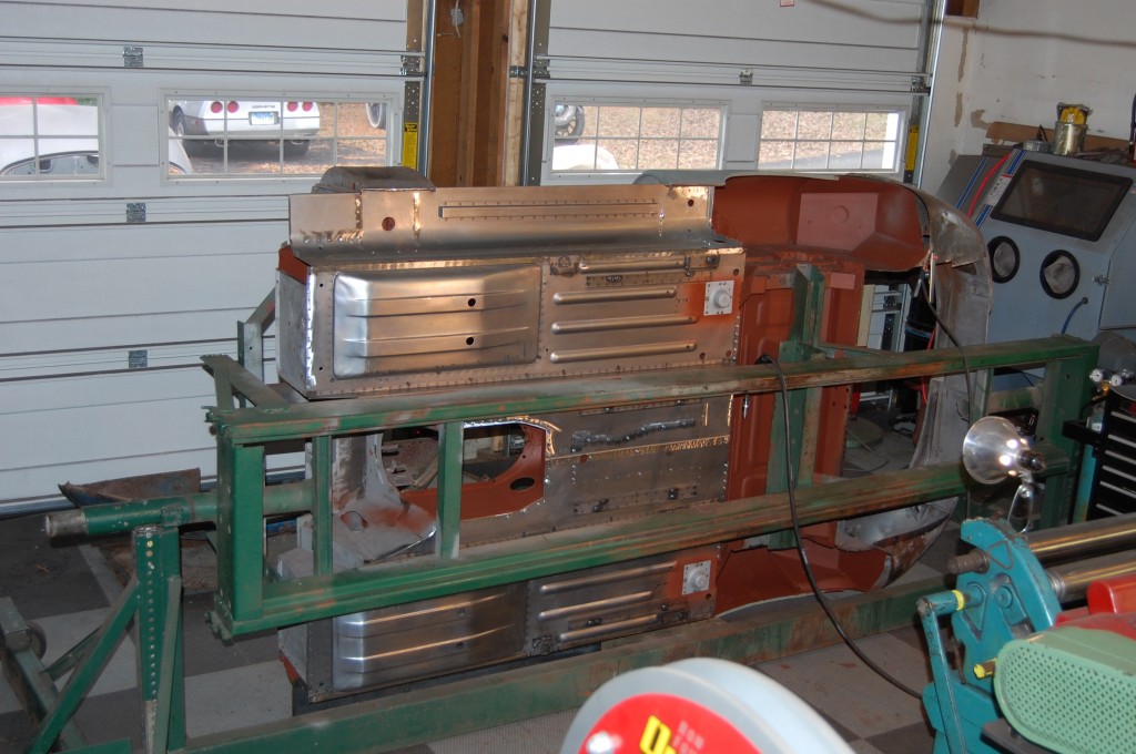
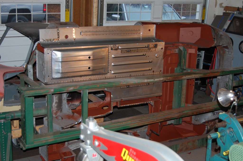
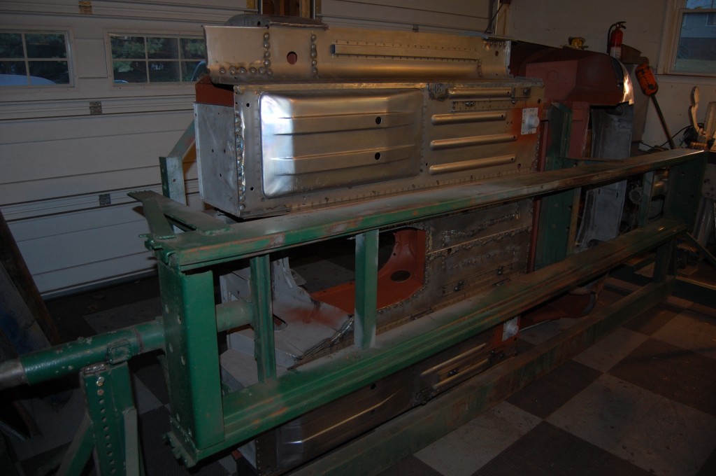
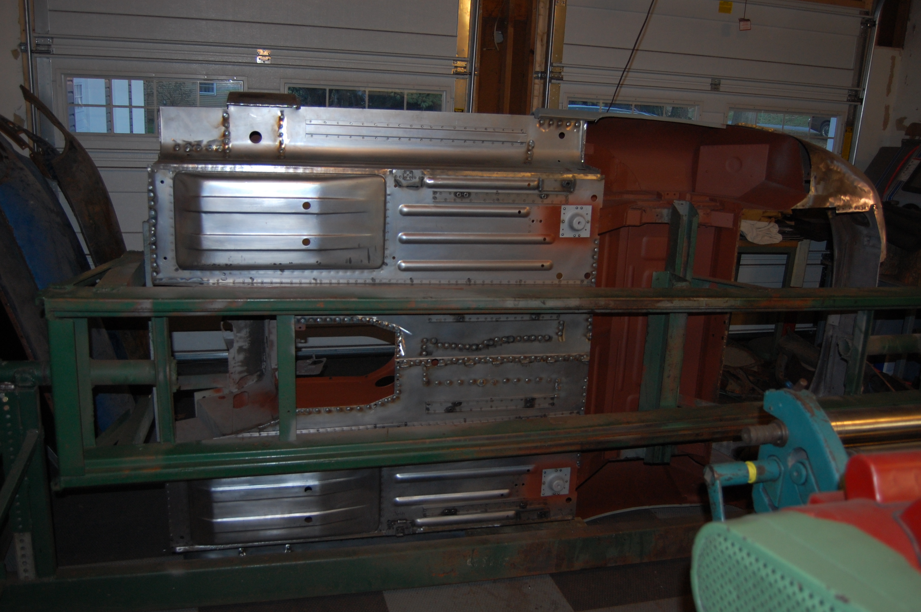
- Once the floors and inner sills are welded up as units, we fit them back to the shell in the same location as before.

-
- Fitment is critical – you can’t take too much time here…
-
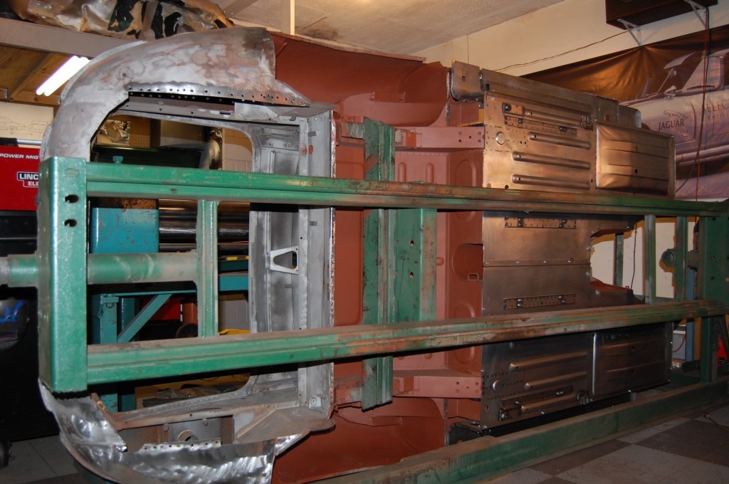
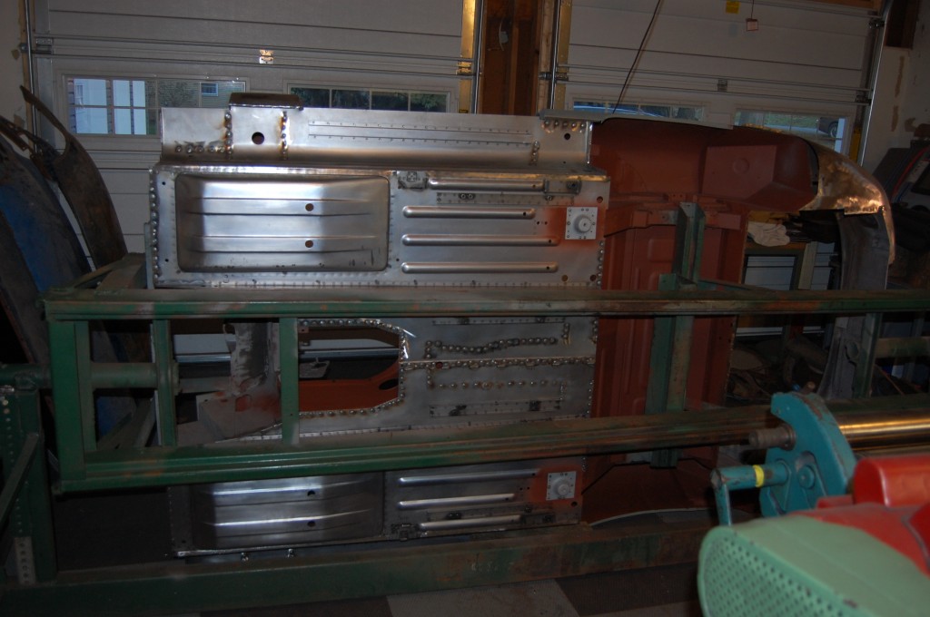
- Now we’re all welded up!

-
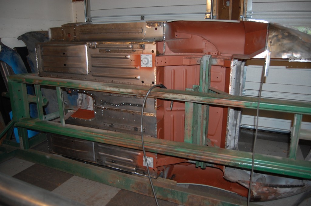
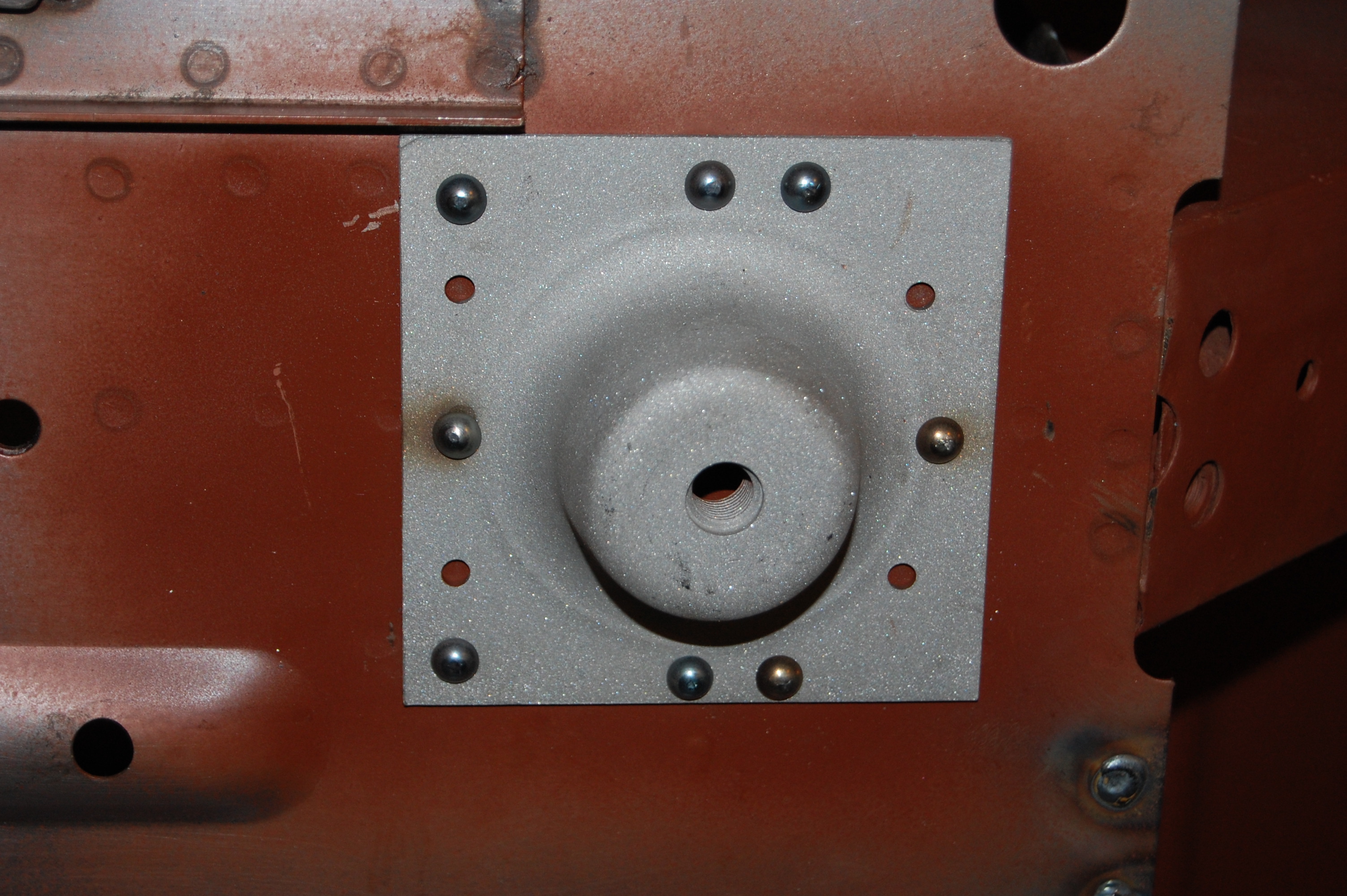
- Note that the radius cups were attached to the floors before the floors were fitted to the shell. Use cold, SOLID rivets here, and weld the top ends to the reinforcement plate, but leave everything “loose” on the bottom side.

-
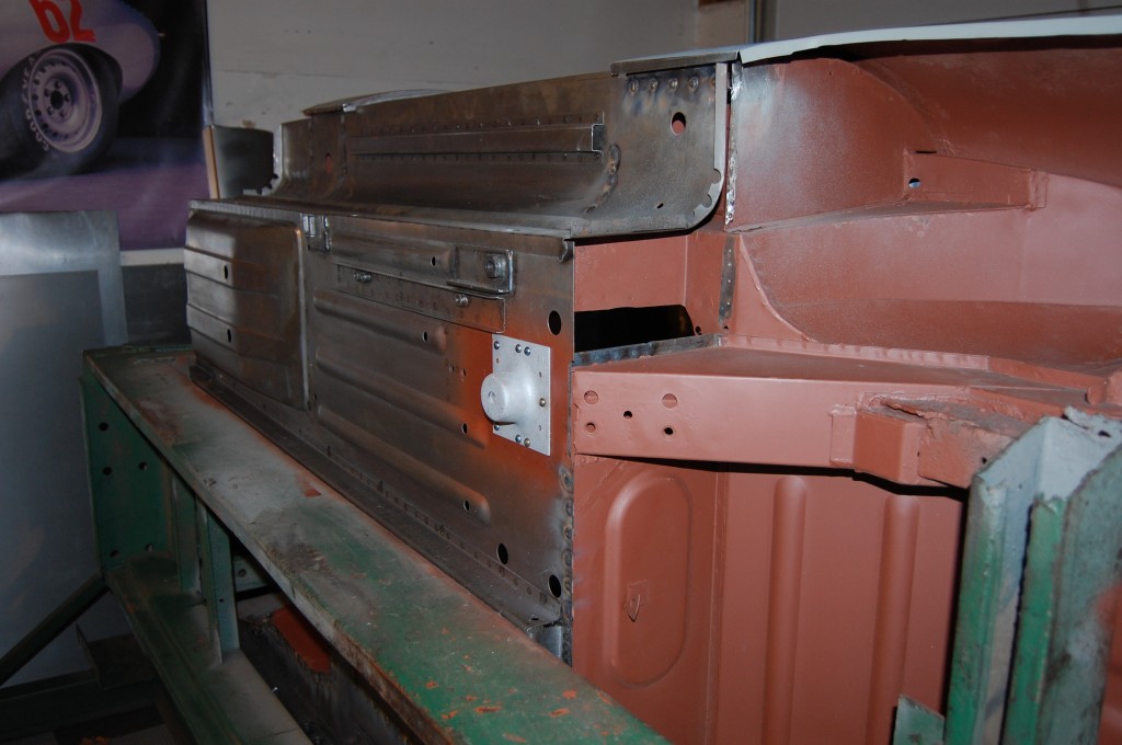
- Another shot of the floors in place. Note that the plug-welds between the floor and inner sill have been ground down smooth so that the outer sill can be fitted.
-
- Look at that fit! There are alot of layers here, and this is a TOUGH area to align and pack everything into place!

-
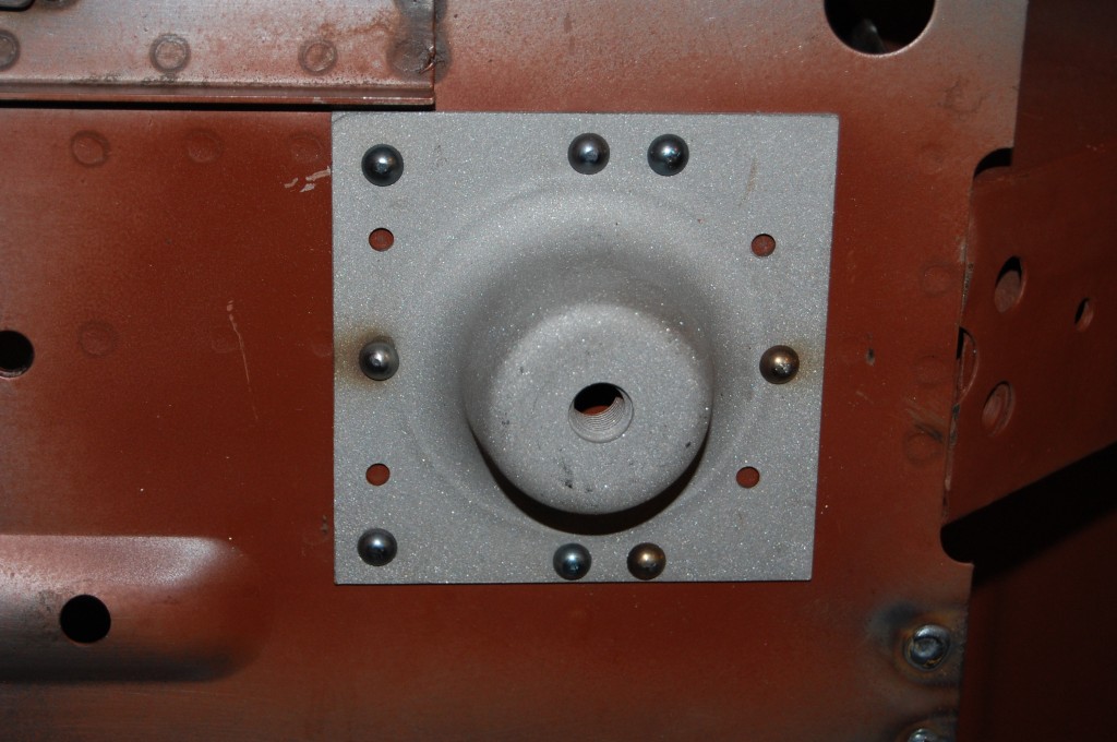
- Note the SOLID rivets, that are NOT welded to the radius cup, and the cup is NOT welded to the floor. You are much better off this way, as welding it solid will eventually lead to metal fatigue and cracks. These cups are drilled for RH and LH 6-cyl. cars, and also V-12’s. Use 8 rivits instead of the factory’s 6 – they only use one on each side depending on right or left – use all 8…
-
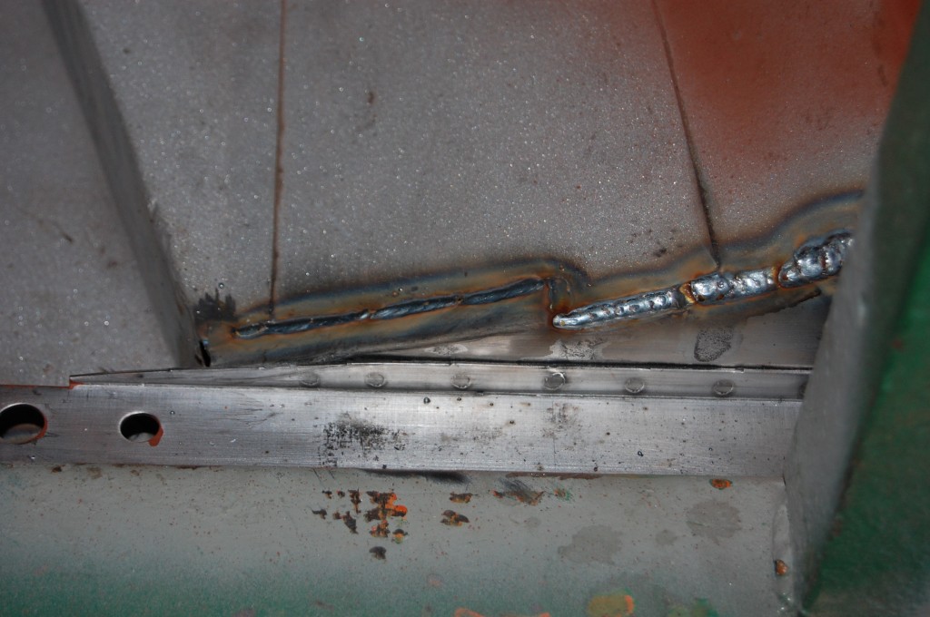
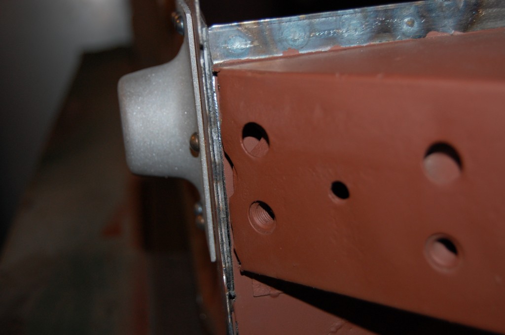
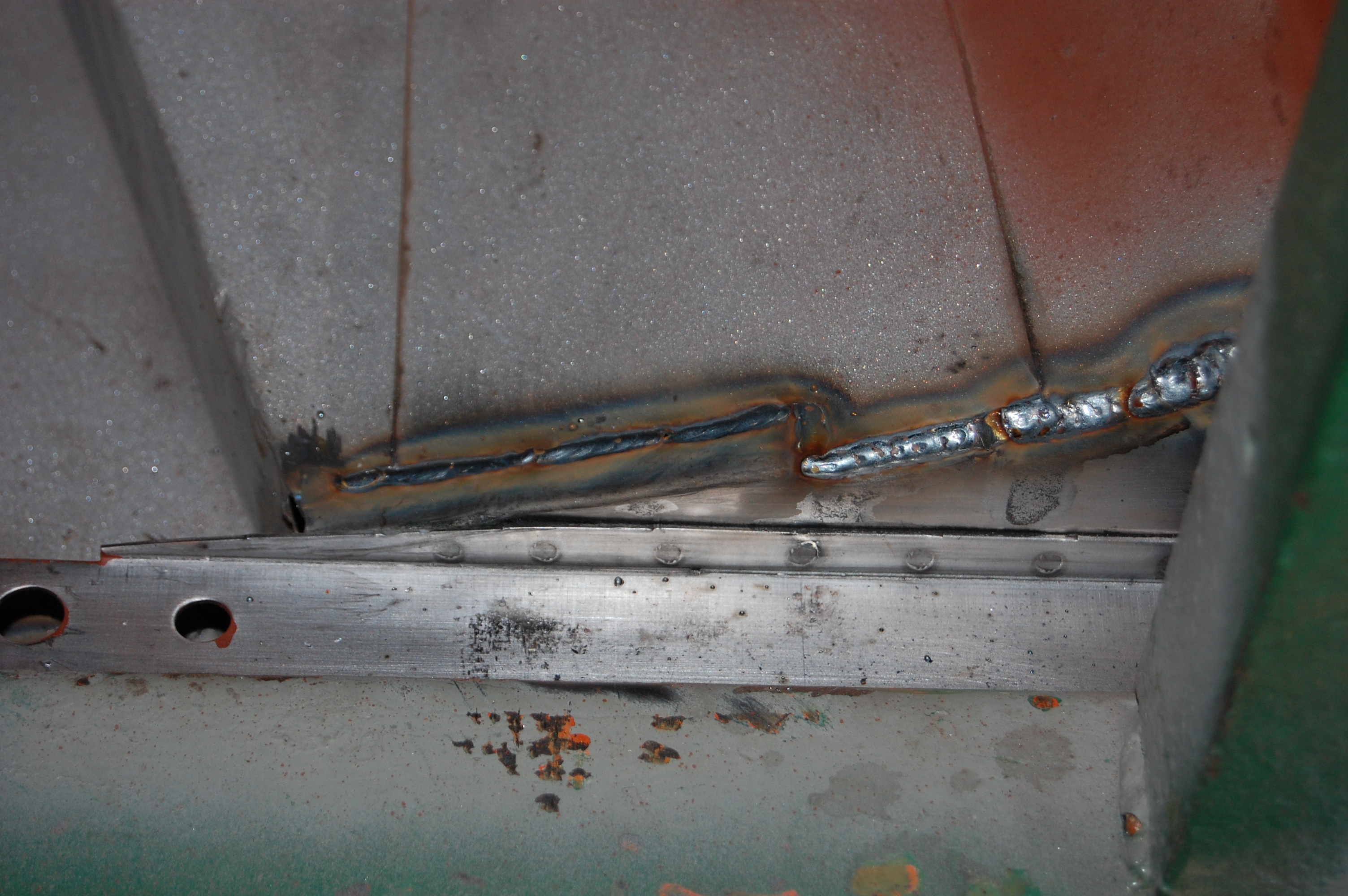
- Here is that area on the RH inner tunnel side that was a little persnickety in the alignment phase. After we were able to hammer over this tab on the new floors, that holds it into place – but is not something we wanted to do in the alignment phase or you can’t get the floor back out! The tunnel was a little messy and thin on it’s bottom flange, so we just ran a nice, strong bead along the whole thing.
-
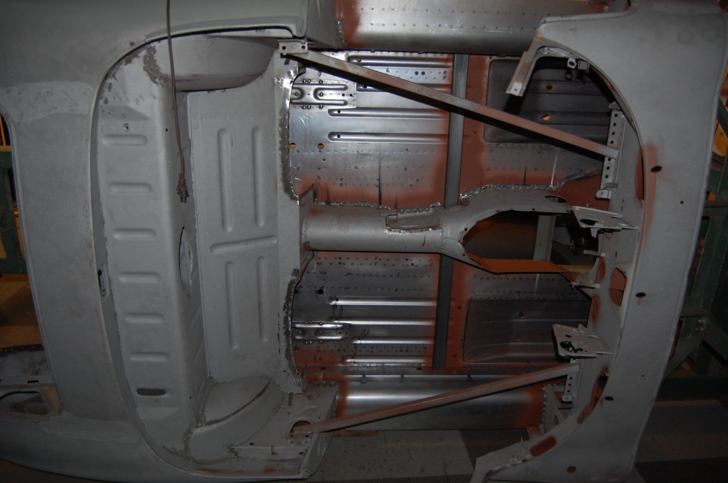
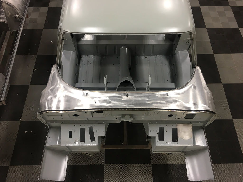
- The floors are in, and we have remembered to slip this subframe tube into place before it is too late! Phew!